Download

1 / 45
620 likes | 1.72k Views
Improving Solder Paste Reflow. Mike Fenner Technical Manager Indium Europe March 2010. Today. Heat transfer and equipment How to profile, variables to consider Understanding and designing the “Best profile” Understanding what the profile does. Heat transfer. Revision

E N D
Improving Solder Paste Reflow Mike Fenner Technical Manager Indium Europe March 2010 Slide 1
Today • Heat transfer and equipment • How to profile, variables to consider • Understanding and designing the “Best profile” • Understanding what the profile does Slide 2
Heat transfer Revision Physics: Transferring thermal energy • Conduction • Radiation • Convection Slide 3
Reflow Equipment • Conduction • Hot plate/travelling hot plate – Thick film guys • Hot bar – Specific components • Soldering iron – Repair, odd form • Induction - Another industry another day Slide 4
Reflow Equipment Leaves Convection • Vapour Phase Reflow[Condensation Soldering] • Forced Air convection Slide 5
Reflow Equipment Vapour Phase Reflow • Single chamber process • Usually batch, can be conveyorised • Boil Inert Liquid • Heated Vapour Condenses on Product (All Surfaces) • Equilibrium process, heat transfer stops at BP of liquid • Not mass, shape or color sensitive • Almost No DT at reflow Slide 6
Vapor Phase Reflow Oven(Batch Style) 1980s • Elegant and simple concept • Temperature rise rate/ RAMP rate??? • Anaerobic? • Cost?? • Mass Production??? • Generally high mix/ low volume/prototyping 21st C Slide 7
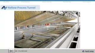
Reflow Equipment Convection/Forced convection • Multi chamber (zone) • Usually always conveyorised • Air/nitrogen is heated and circulated • Provides Even Heat • Moderate Price • Not usually, but can be, in equilibrium • The dominant technology Slide 8
Convection Reflow Ovens:Dominate the Industry Courtesy: Electrovert Slide 9
Before we go any further • There is no universal best profile • Profile is not determined by the paste • Profile is not determined by the PCBA • Profile is not determined by the reflow oven • It’s a combination – and that combination is unique to you • Mostly its determined by the efficiency of the oven and the workload. Paste is secondary • Any Recommended Profile is therefore just a strong suggestion Slide 10
Classic Profiling concept Z7 Z1 Z2 Z3 Z4 Z5 Z6 Z7 Cooling Cooling Z1 Z2 Z3 Z4 Z5 Z6 Slide 11
T Peak Temp Liquidus Temp Soak Exit Temp Soak Entry Temp Heating Rates °c/s Soak time t Time Above Liquidus RAMP SOAK Reflow COOL Capturing a temperature profile • Thermocouples are attached to components on the PCBa • The temperature of the components is measured as the PCBa passes through the oven and is soldered. • There are 2 basic methods…. Slide 12
Fishing wire method • Uses oven/external measurement system and long thermocouples • Practical only on small ovens • Measurements tend to be more variable • Assembly is easily snagged and damaged on moving conveyor parts Slide 13
So in practice - how do you determine best profile? • Use a data logger or Profiler • Use predictive software with SPC • What is the ‘best profile’? Slide 14
Thermal Profilers Slide 15
Process Variables • Oven type and settings • Solder paste and flux • Board finish • Components – technology • PCB substrate and layout • Throughput Slide 16
The Lead Free Challenge • Component Integrity Max package temperatures currently 235-240C Excess heating has unknown effect on device MTBF Widespread use of ‘delicate’ package types. • Reduced process window Lead free pastes have liquidus temp 30-40C higher than Sn/Pb Slide 17
Sn/Pb process window • Illustration for standard Sn63/Pb37 solder paste (TLiq = 183C) • Solder paste spec specifies min peak of 205 C for good wetting • Component maximum is 235C Peak Temp Deg C TOO HOT 235 30C OK 205 TOO COLD WE HAVE A 30C PROCESS WINDOW TO WORK WITH ! Slide 18
SAC process window • Illustration for lead free SnAgCu solder paste ( Tliq = 217C) • Solder paste spec specifies min peak of 227 C for good wetting • Max Peak ideally is 257C but component max is still 235C Peak Temp Deg C TOO HOT 235 8C OK 227 TOO COLD WE NOW HAVE AN 8C PROCESS WINDOW TO WORK WITH ! Slide 19
Reduced process window • Oven needs to maintain small delta T across the board. • Profiles need to be developed for each board type • Periodic profiling required to monitor and maintain process Slide 20
Pass through profiling system method - AKA Data Logger • Follows the PCBa through the reflow oven • Data logger must be protected from the heat • Can be used on large or small ovens • Generally more accurate and repeatable • Must be small to pass through restricted oven tunnels • Should be narrow to allow profiling of small PCB’s Slide 21
Methods of thermocouple attachment Slide 22
Where to attach TC’s ? • Aim is to heat the board uniformly • Components vary in size, mass, texture and colour. • PCB’s vary is size, shape, mass, component densities • Need to identify extremes of the profile envelope. Slide 23
Some pointers … • High mass/bigger components will heat up slowest • Low mass/smaller components will heat up fastest • Power components with integral heat-sinks • Components connected to large copper ground planes • Indirectly heated components ( BGA ) • Components nearer board edges • Components nearer the centre / densely populated • Components shadowed by others Slide 24
Profiling do’s and don'ts • DO make the TC leads long enough so that the profiler follows at least 1 zone behind the PCB. • DON’T pass the profiler through the oven first, always behind the PCBa. • DO profile an example of the actual board being processed. • DON’T profile the test board again before it has returned to ambient temperature. • DO profile a populated board. Slide 25
Profile Prediction • Allows the effect of heater and belt-speed set-point changes to be predicted • Saves time and money by eliminating the need to perform unnecessary profile runs for set-up and fine tuning • Reduces machine downtime by allowing process set-up to be completed offline. • Eases process set-up and change over to Lead Free paste • Unique graphical approach intuitively provides guidance to the user to optimise the process • Quickly allows the user to evaluate the effect of paste changes on the process. Slide 26
Optimising Reflow Conventional / New Profiles Common Defects Ideal Profile Design Slide 27
Do a proper DoEProprietary/Predictive Programs with SPC Ours is ReflowCoach™ Slide 28
Or use SPC tools which come with good profilers • Instantly produces run charts for each process parameter • Also calculates XBar,σ,Cp and Cpk • Source data selected from profile database Slide 29
Splatter, thermal shock Insufficient solvent evaporation Oxidation, too much flux activation Insufficient flux activity TAL Long/Hot: IM too thick, component damage Short/Cool: trapping of flux, voids Too fast: thermal shockToo slow: large grains=> weak joint Potential Reflow Problems 5 3 4 1 6 2 Slide 30
Conventional Profile Design IR sensitive to variation in parts feature. Soak zone helped to reduce temperature gradient Slide 31
Optimized reflow profile via defect mechanisms consideration Slow ramp-up to 195°C, gradual raise to 200°C, spike to 230 °C, rapid cool down. Slide 32
Defect Mechanisms Analysis • Tombstoning / Skewing • uneven wetting at both ends of chip Slide 33
Defect Mechanisms Analysis - II • Wicking / Opens • leads hotter than PCB • slow ramp up rate to allow the board and components reaching temperature equilibrium before solder melts; more bottom side heating Slide 34
Defect Mechanisms Analysis - III • Solder balling • spattering (slow ramp up rate to dry out paste solvents or moisture gradually) • excessive oxidation (minimize heat input prior to reflow (slow ramp up rate, no plateau at soaking zone) to reduce oxidation) Slide 35
Defect Mechanisms Analysis - IV • Hot slump / Bridging • viscosity drops with increasing temperature • slow ramp up rate to dry out paste solvent gradually before viscosity decreases too much Slide 36
Defect Mechanisms Analysis - V • Solder beading • Slumping (Viscosity drops w/ increasing temperature) • Spattering (Rapid outgassing under low standoff components) Beading is more often a result of poor aperture design Slide 37
Defect Mechanism - VI • Poor wetting • excessive oxidation(minimize heat input prior to reflow (minimize soaking zone, or use linear ramp-up from ambient to solder melting temperature) to reduce oxidation) Slide 38
Defect Mechanisms Analysis - VII • Voiding • excessive oxidation (minimize heat input prior to reflow (minimize soaking zone, or use linear ramp-up from ambient to solder melting temperature) to reduce oxidation) • flux remnant too high in viscosity (cooler reflow profile to allow more solvents in flux remnant) Slide 39
Defect Mechanisms Analysis - VIII • Charring - dark flux residue • Leaching - grainy solder joint appearance • Dewetting - uneven pad wetting • Excessive Intermetallics - poor joint reliability • overheat (lower temperature, shorter time above Liquidus) Slide 40
Voiding changes things Slide 41
Summary • Temperature profiling forms a key part of lead free processing. • Used in both process setup and ongoing process control • Modern profiling equipment has extensive tools to help setup and maintain your lead free process. Slide 42
Further reading: In depth explanation of what we’ve just seen Slide 43
Component Placement 15% Reflow 15% Finally Solder Paste Screen Printer 64% Incoming Components 6% Optimizing printing and reflow processes can alleviate almost 80% of defects. Slide 44
That’s it • Thank you for your attention • Questions Acknowledgements and thanks to Solderstar for their assistance in preparation of this presentation www.solderstar.co.uk Slide 45