Download
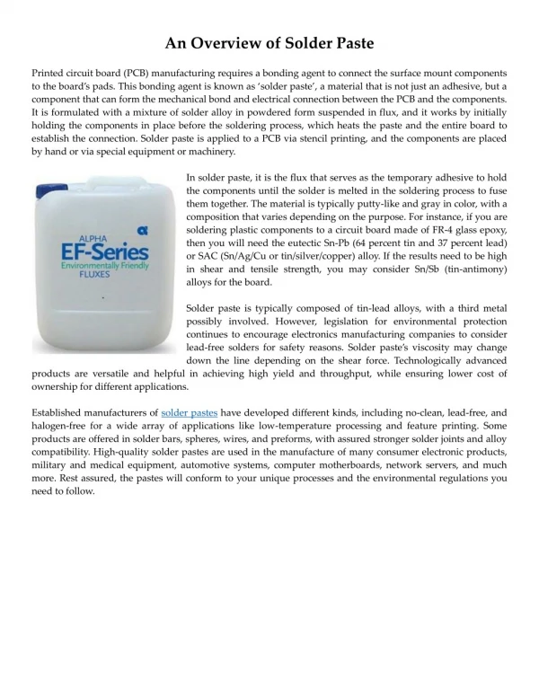
1 / 38
400 likes | 436 Views
Deposition of Solder Paste into High Density Cavity Assemblies. Fernando Coma Jeffrey Kennedy Thilo Sack. Aggressive space reduction and density increase. Presentation Name | Month 00 2007.

E N D
Deposition of Solder Paste into High Density Cavity Assemblies Fernando ComaJeffrey KennedyThilo Sack CELESTICA INC
Aggressive space reduction and density increase. CELESTICA INC Presentation Name | Month 00 2007
Evaluate the practical limits of integrating PWBs with cavities into a standard IPC 610 Class 3 process CELESTICA INC DEPOSITION OF SOLDER PASTE INTO HIGH DENSITY CAVITY ASSEMBLIES| Month 02 2015
3 Solder Deposition Techniques which were evaluated: Step stencil Dispensing Jetting CELESTICA INC DEPOSITION OF SOLDER PASTE INTO HIGH DENSITY CAVITY ASSEMBLIES| Month 02 2015
test vehicle Size: 185x60 mm CELESTICA INC DEPOSITION OF SOLDER PASTE INTO HIGH DENSITY CAVITY ASSEMBLIES| Month 02 2015
10x5 12x12 20x18 30x15 30x40 15x15 5x5 10x10 17 cavities • Cavity sizes (mm): • 30 x 40 • 30 x 15 • 20 x 18 • 15 x 15 • 12 x 12 • 10 x 10 • 10 x 5 • 5 x 5 CELESTICA INC DEPOSITION OF SOLDER PASTE INTO HIGH DENSITY CAVITY ASSEMBLIES| Month 02 2015
3 cavity depths • Cavities fabricated by AT&S (patented process) • Factors when choosing depth: • Match the common thicknesses of SMT components • Available pre-preg used in the stack-up of the PWB • Depths: • 0 (TOP surface) • 150 um • 300 um CELESTICA INC DEPOSITION OF SOLDER PASTE INTO HIGH DENSITY CAVITY ASSEMBLIES| Month 02 2015
4 component types For chip components, “density” is the minimum spacing between devices while for CSP’s, “pitch” if the device I/O minimum pitch evaluated. CELESTICA INC DEPOSITION OF SOLDER PASTE INTO HIGH DENSITY CAVITY ASSEMBLIES| Month 02 2015
DFx RULES CELESTICA INC DEPOSITION OF SOLDER PASTE INTO HIGH DENSITY CAVITY ASSEMBLIES| Month 02 2015
1st – step stencil Challenges: Stencil manufacturing is key for this technology. Density into cavities is depending on stencil design. CELESTICA INC DEPOSITION OF SOLDER PASTE INTO HIGH DENSITY CAVITY ASSEMBLIES| Month 02 2015
stencil material used • Fine grain stainless steel used for stencil Std. 390 SS on Left and Fine Grain SS on Right CELESTICA INC DEPOSITION OF SOLDER PASTE INTO HIGH DENSITY CAVITY ASSEMBLIES| Month 02 2015
stencil fabrication CELESTICA INC DEPOSITION OF SOLDER PASTE INTO HIGH DENSITY CAVITY ASSEMBLIES| Month 02 2015
squeegees Challenges: Alignment between blade and stencil. Cuts are needed to allow blade go into the cavities. Blade support used to increase pressure into cavities. CELESTICA INC DEPOSITION OF SOLDER PASTE INTO HIGH DENSITY CAVITY ASSEMBLIES| Month 02 2015
blade alignment: stencil & PCB • Set up considerations CELESTICA INC DEPOSITION OF SOLDER PASTE INTO HIGH DENSITY CAVITY ASSEMBLIES| Month 02 2015
screen printer cycle • Screen printer video
Without blade support With blade support blade support • Using backside squeegee blade support improves print performance significantly • However each cavity requires different amount of backside support CELESTICA INC DEPOSITION OF SOLDER PASTE INTO HIGH DENSITY CAVITY ASSEMBLIES| Month 02 2015
trials • Blade support to create pressure • Blade behavior across the entire width of the board • Transference into cavities [01005 (0402) / 0402 (1005) / CSP apertures] Chip 0402 & 0201 volume CSP Inside vs Outside of Cavity CELESTICA INC DEPOSITION OF SOLDER PASTE INTO HIGH DENSITY CAVITY ASSEMBLIES| Month 02 2015
step stencil summary • Possibility of soldering all chip component types into cavities [includes down to 01005 (0402) sized chips] • Able to accommodate different depth cavities, limitations comes from stencil manufacturing. • Low cycle time as standard screen printer is used. • More work required to support different depths and apertures in the same stencil. CELESTICA INC DEPOSITION OF SOLDER PASTE INTO HIGH DENSITY CAVITY ASSEMBLIES| Month 02 2015
2nd - dispensing • Micro piston used dispenses a single shot per pump cycle. • Able to dispense dots for 01005 (0402) components. • Programmable to dispense at any height. • Requires the use of special solder pastes designed for dispensing. CELESTICA INC DEPOSITION OF SOLDER PASTE INTO HIGH DENSITY CAVITY ASSEMBLIES| Month 02 2015
dedicated solder paste Dedicated solder paste is required for this process as the head needs small particles, high flux content and special formulation to do the dispensing CELESTICA INC DEPOSITION OF SOLDER PASTE INTO HIGH DENSITY CAVITY ASSEMBLIES| Month 02 2015
dispensing machine cycle • Dispensing video
1 dot for each 01005 (0402) 5 dots for each 0201 (0603) • Parameters defined to dispense solder paste for 01005 (0402) component. • Same parameters were used to dispense multiple dots for large parts. • 0402 (1005) size pads needed up to 60 single dots. CELESTICA INC DEPOSITION OF SOLDER PASTE INTO HIGH DENSITY CAVITY ASSEMBLIES| Month 02 2015
dispensing summary • Possibility of soldering all chip component types into cavities [includes down to 01005 (0402) sized chips] • Able to accommodate different depth cavities without any restrictions. • For production it is ideal to choose a machine that supports multiple dispense heads to reduce overall cycle time. • Cycle time depends on the needle used to create dispensed dot sizes. CELESTICA INC DEPOSITION OF SOLDER PASTE INTO HIGH DENSITY CAVITY ASSEMBLIES| Month 02 2015
3rd - jetting • Requires the use of special solder pastes designed for jetting. • Minimum dot size able to be dispensed is 300um diameter [0201 components, (0603)] Impacts ability to handle smallest parts. • Max. dispense height limits CELESTICA INC DEPOSITION OF SOLDER PASTE INTO HIGH DENSITY CAVITY ASSEMBLIES| Month 02 2015
dedicated solder paste Dedicated solder paste is required for this process as the head needs small particles, high flux content and special formulation to do the jetting CELESTICA INC DEPOSITION OF SOLDER PASTE INTO HIGH DENSITY CAVITY ASSEMBLIES| Month 02 2015
jetting machine cycle • Jetting video
3 heights tested • Ideal dispense height above the board surface is 650um, although increasing distance up to 850um does not impact accuracy. • Establishing datum to effectively jet into the cavities is critical (reference points) • Assessed impact of dispensing into cavities from heights > 650um on deposit consistency CELESTICA INC DEPOSITION OF SOLDER PASTE INTO HIGH DENSITY CAVITY ASSEMBLIES| Month 02 2015
jettingheightvspositionalaccuracy Comp 0201 (0603) Cavity: 150um Dispense height: 650um Comp 0201 (0603) Cavity: 150um Dispense height: 1800um CELESTICA INC DEPOSITION OF SOLDER PASTE INTO HIGH DENSITY CAVITY ASSEMBLIES| Month 02 2015
flexibility CELESTICA INC
CLASS 3 CELESTICA INC Presentation Name | Month 00 2007
jetting summary • Machine is capable for both processes (two head heights) and for different volumes (minimum 6.8 nl and maximum 51nl) • IPC 610 Class 3 solder joints are achievable using jetting process for both 0402 (1005) and 0201 (0603) components • Jetting machine is supposed to feed a pick and place machine mounting 40,000 components per hour. This data depends on the geometry of the PCB to be produced. • Dispense strategy for each package can easily be controlled via simple software changes • Standard jetting height is 650um, but working with the supplier this distance could be adapted to something less CELESTICA INC DEPOSITION OF SOLDER PASTE INTO HIGH DENSITY CAVITY ASSEMBLIES| Month 02 2015
summary • Transferring solder paste into high density cavities is a process that can be done with high quality and capable of achieving IPC 610 class 3 standard solder joints. • The most appropriate and cost effective method to use will depend on the final product configuration since each method did have its own limitations in terms of capability to support certain design features or cycle time CELESTICA INC DEPOSITION OF SOLDER PASTE INTO HIGH DENSITY CAVITY ASSEMBLIES| Month 02 2015
recommended deposition method based on package type CELESTICA INC DEPOSITION OF SOLDER PASTE INTO HIGH DENSITY CAVITY ASSEMBLIES| Month 02 2015
process decision matrix • Several factors must be considered to integrate the most appropriate solder deposition method depending on product design and desired manufacturing setup
Acknowledgements • Jeff Kennedy, Thilo Sack, Vicenta Jorge, Samuel Plasencia, Javier Canillas, Miguel Sanchez (Celestica), Euripides BOB Partners: Thales TCS & TGS, AT&S. • Mydata / AB Electronics (Jetting) • GPD (Dispensing) • Great Lakes Engineering / Pantur (Stencils) • Indium (Solder Paste) CELESTICA INC DEPOSITION OF SOLDER PASTE INTO HIGH DENSITY CAVITY ASSEMBLIES| Month 02 2015
Questions? CELESTICA INC DEPOSITION OF SOLDER PASTE INTO HIGH DENSITY CAVITY ASSEMBLIES| Month 02 2015