Download
1 / 77
790 likes | 1k Views
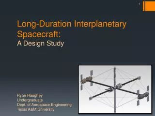
Long-Duration Interplanetary Spacecraft: A Design Study. Ryan Haughey Undergraduate Dept. of Aerospace Engineering Texas A&M University. Project Overview. Design project for aerospace engineering students in final year of undergraduate program

E N D
Long-Duration Interplanetary Spacecraft: A Design Study Ryan HaugheyUndergraduateDept. of Aerospace Engineering Texas A&M University
Project Overview • Design project for aerospace engineering students in final year of undergraduate program • Subgroups developed initial goals, which were later integrated into a final spacecraft • Presented to board of industry and academic reviewers in Dec. 2012
Mission Statement “To expand the domain of humanity beyond the earth for the betterment, preservation, and advancement of all humankind by creating a self-sustaining, mobile habitat that ensures the physical and psychological well-being of its inhabitants.” • >24 Month Trip Time • 12 Crew Members • Capable of Interplanetary Space Travel
What’s the Purpose? • Scientific • Advance the state of the art in diverse technological areas • Innovations for space usually have important terrestrial applications • Economic • Mining of asteroids could yield many valuable materials • High demand for space tourism, research opportunities • Exploratory • Spark a new age of enthusiasm for the sciences • Inspire next generation of scientists and explorers
Ultimate goal • Attain economic viability and sustainability of the interplanetary habitat through a range of revenue-generating activities, primarily mining of asteroids
Design DriversDetailed DesignCompetitive Advantages Presentation Outline
Design DriversDetailed DesignCompetitive Advantages Presentation Outline
Design Goals • Elements of a viable system • Livability – Crew must be able to function, survive • Practicality – Magic solution will not appear, must deal with proven feasibility of technology • Modularity – Assembly must be simple, repairs must be efficient, expansion must be an option
Challenges of a Interplanetary Space • Physiological • Physiological • Weightlessness • Livability • Radiation • Cost barriers to entry
Design Driver: Physiological Factors in Prolonged Spaceflight No human being has ever traveled into interplanetary space In 5 decades of manned spaceflight, our understanding of physiological change during long duration missions remains limited Physiological impacts are significant and varied During the course of a mission: 0-g effects (bone loss, muscle loss, immune system impairment, etc.), radiation exposure and immunological depression Return to Earth: cardiovascular de-conditioning and orthostatic intolerance Both in-flight and post-flight physiological issues must be countered
Design Driver: Countering 0-g Effects There is no completely satisfactory approach to countering 0-g effects aside from sustained artificial gravity. We do not know how much “g” is required to maintain human health indefinitely (besides zero g = bad, and one g = good) We will not know the answer to this for a long time, since long term experiments are required. Therefore, in this design study, we require: 1 g artificial gravity. Acceptable levels of Coriolis effects Exposure to 1g almost all the time
Countermeasures – Artificial Gravity Artificial gravity becomes more “normal” with increasing radius 0.035 g Limit of low traction 1g Comfort zone 4 rpm Onset of motion sickness 6 m/s rim speed Apparent gravity depends on direction of motion 1 To avoid motion sickness, we must rotate below 4 rpm (while keeping the rotation radius as small as possible)
Physiological Factors Size and Rotation Rate 1 g artificial gravity and acceptable levels of Coriolois forces motivate: Rotation rate = 3.5 rpm Rotation radius = 70m (Thus max dimension can’t be less than 140m) Exposure to 1g almost all the time means entire s/c must rotate (a separate wheel with an attached zero-g component is not practical)
Design Driver: Interplanetary Space Environment High levels of radiation present in interplanetary space Material must limit radiation exposure to levels on par with ISS astronauts Micrometeorite protection must also be included Livable temperature must be maintained
Design Driver: Mass Support needed to keep structure together Launch costs are around $2,000 per pound of material Standard trusses would add unnecessary mass; alternative solution needed
The crew has to breathe! 2 Total pressure = ½ atm
What Shape? ½ Atm pressurization & centrifugal loading Solids of revolution are the most efficient pressure vessels 1 Torus Minimum ratio of pressurized volume to useful floor space Rotation axis = axis of maximum inertia Attitude is passively stable Sphere Large ratio of pressurized volume to useful floor space (projected area) Long cylinder Axis of minimum inertia = rotation axis Energy dissipation results in disruptive nutation Active attitude control of this = one more thing to go wrong
How Much Space Do People and Plants Need? Total Projected area per person = 40 m2 Total Volume per person = 1050 m3 Note: This is Table 3.2 of cited reference 2, but with several categories of space removed owing to the limitations of a 12-person vessel. The spaces removed are: Shops, schools and hospitals, public open space (500 m3) service industry space, transportation and animal areas.
Is a Complete Torus Too Roomy? 1 z, zb 2 r R y, yb x, xb With R=70m, r=5m and three “floors”: Projected area ~ 10X2RX3 ~ 12,600 m2 Enough for 315 people! But we only need to sustain 12 …..
Solution: Use only what you need! Embed the hab modules in a stiff, light tensioned cable, compressed column structure – a proven approach to precision space structures. Cables carry most of the centrifugal loading Junctions are statically determinite, permitting accurate analysis Stiffness is provided in all six rigid body hab module degrees of freedom. Lowest vibration modes avoid frequencies that induce motion sickness Design is expandable by adding more hab modules and more supporting cables • Note: • A truss and walkway connect the hab modules (with each other and with agrimodules) • Cross truss and rotation axis column serve to give sufficient stiffness. • Cross truss supports agg modules • Propulsion engines located at tips of cross truss. Protects Hab and Agg modules from radiation. Provides control authority for both cm acceleration and rotation control • Modular pod configuration • Attach modules as needed to support volume requirements • Addressing new challenges • Vibration damping using tensioned cables and compression columns • Natural frequencies causing motion sickness are avoided • Capitalizing new advantages • Engines may be placed along outer radius of structure without interfering with livable area
Mission Requirements • Minimize delta-v required for transportation • 2-3 year mission duration Solution • Constant thrust departure from LEO to Lagrange points • “Grand Tour” of interplanetary space in Earth – Sun system • Drift along energy boundary of Earth-Sun system with little to no delta-v • Orbit cycle used by many asteroids, could allow for rendezvous and mining
1 • Start in 300 km circular orbit about Earth • Thrust always aligned with the velocity vector • Full thrust up until 11 days and coasting to L1 thereafter • Spiral out to a coasting trajectory to the E-M L1 “throat”. • Meld into the Lyapunov orbit of L1 Station and refuel • Propellant mass: 21 MT • Trip duration: 5.6 months Initial Deployment: Spiral out to E-M L1
Orbit of the Moon L1 Lyapunov Orbit Moon • After refueling, leave L1 on the outward invariant manifold. • Swing by the Moon and exit the E-M L2 throat in time to meld with a heteroclinic orbit leading to the Sun-Earth L2 • Take one turn around the Lyapunov orbit and enter the external domain of the Sun-Earth system From E-M L1 to S-E L2: Start of the First Grand Tour E-L1 to S-L2: V=12m/s, 50 days 1 122,720 km L1 L2 Sun L2 Earth-Moon Frame Sun-Earth Frame
1 • Drop off cargo at L1 Station. Leave L1 Lyapunov orbit. Follow heteroclinic orbit to L2 (pink line, left to right) (drop off cargo at Earth-Moon system) • Meld into L2 Lyapunov orbit, follow for ¾ of a period, then follow the unstabile manifold (green line, heading down) Asteroid Mining Tours: Exterior Realm L1 L2 3.0 million km Sun-Earth Frame
Apophis Sun 3-2 resonance 1 Through S-E L2 to the Grand Tour of the Exterior Realm 3. Follow the homoclinic, exterior domain orbit (green path issuing from L2 and going clockwise) 4. Mine Amors and Apollos on the way (3 years) Then: see next slide 1 AU
1 • Follow homoclinic exterior domain orbit to L2 on the stable manifold (green line, pointing down, left). Refurbish and repair at L2 Station • Meld into L2 Lyapunov orbit, follow for ½ of a period, then follow the heteroclinic orbit to L1 (pink line, right to left). Heteroclinic Transfer Between Exterior and Interior Realms L1 L2 3.0 million km • Deliver cargo to Earth-Moon system. Meld into L1 Lyapunov orbit, Exchange crew and refuel at L1 Station. • Follow Lyapunov orbit for one period, then follow the homoclinic interior domain orbit (blue line heading to the left).
1 Through S-E L1 to the Grand Tour of the Interior Realm 9. Follow the homoclinic, interior domain orbit (red path issuing from L1 and going counter clockwise) 10. Mine Atens and Apollos on the way (two years) 11. Then follow the stable manifold to L1 (blue line in previous slide, heading to the right). 12. Refuel and exchange crew at L1 station. Go to step 1 and repeat. Forbidden zone Apophis Sun 3-2 resonance
Design DriversDetailed DesignCompetitive Advantages Presentation Outline
Life Support Management PM: Ryan Haughey Assistant PM: Blaise Cole SystemTeams System Architecture Stress & Thermal Propulsion Budget & Scheduling Power
Life Support System Overview – ArchitectureMichael Pierce, Paola Alicea, Terry Huang, Luis Carrilo, Christopher Roach, Mario Botros Management System Architecture Goal: Synergize design concepts to meet functional requirements Challenges: • Physiological: radiation, bone loss, air • Psychological: confinement, productivity • System stability Stress & Thermal Propulsion Budget & Scheduling Power
Moment of Inertia Overview z x,y,z axes = Principal axes of inertia Ixx = 203,300 MT-m2 Iyy = 463,600 MT-m2 Izz = 641,300 MT-m2 Total Mass = 350MT 15MT 18MT 23MT y x 46MT (total) Izz is largest moment of inertia; rigid body nutation of the spin axis due to energy dissipation coupling is suppressed 4MT
Architecture Overview Nuclear Reactor and Engine Water Ballast 40 m 70 m 70 m 17 m 40 m Living Area Agriculture Pods Airlock/Dock
Modeled on NASA Transhab study (Inflatable pod) Nearly 2 dozen layers in 1-ft thick skin provide thermal, ballistic, and radiation protection Radiation Protection: conservatively 30 rem/yr (ISS is 50 rem/yr) Ballistic Protection: Micrometeorite and Orbital Debris Shield Each pod provides living space for four crew members Inflatable Living Pod 6 m 32.5 m 8.4 m 10 m 13 m
Identical to living pods Low-gravity environment: sufficient to allow for proper survival by plants One pod optimized for food growth, other for oxygen generation Auxiliary pods
Engine & Power Pods • Provides housing for power plant and engine • Power plant selected as nuclear reactor (further discussion later) • Shielding for nuclear reactor assists structure in deep space radiation and micrometeorite protection
Water Ballast • Stores system water • Displace water along structure length to adjust moments of inertia • Thermal management of water could be accomplished using heat pipes from power source • High levels of redundancy needed to protect against micrometeorite impacts on water column
Docking Module • Standardized module allows for docking of rendezvous craft • ISS PIRS module may serve as good model • Combination docking port and airlock Image credit: NASA
Life Support System Summary – Architecture Management System Architecture Goal: Synergize design concepts to meet functional requirements Findings: • Modular, inflatable habitation pods • Water ballast • Locate power, engine away from the axis of rotation Stress & Thermal Propulsion Budget & Scheduling Power
Goal: Create an environment conducive to healthy human functions with minimal re-supply for duration of mission Challenges: • Crew nutrition & health • Water recycling & distribution • Waste Management • Oxygen regeneration 40 System Overview – Life SupportMegan Heard, Sarah Atkinson, Mary Williamnson, Jacob Hollister, Jorge Santana, Olga Rodionova, Erin Mastenbrook Life Support Management System Architecture Stress & Thermal Propulsion Budget & Scheduling Power
Crew Nutrition • Modeled on diet of residents of Greek island of Ikaria, noted for exceptional health and longevity • For missions past 21 months, more practical to self-sustain food • Some portions of diet require bringing food along (meats, oils) • Proposed solutions: • Aeroponically grow food in low-gravity agriculture pods • Maintain cold storage for stowed perishable food Image credit: Tower Garden
Nutrition Logistics Stored food consists of all which can not be grown in tower gardens. Includes: meats, grains, sugars, salts, & milk Tower gardens used to grow range of fruits, vegetables, and herbs. Shelf used to grow potatoes Combination of produce and stored food allow for full sustainment of crew for around 3 years
Water Treatment • Must handle waste-water and gray-water • Prevent disease development • Effective water recycling becomes advantageous after 0.5 months • Proposed solution • Utilize ECLSS system currently in place on ISS (~95% efficient)
Waste Management • Isolation of outpost requires full effective recycling • Human waste can serve as effective crop fertilizers, reducing need for artificial fertilization (added mass) • Proposed solutions • Closed-loop system with high-efficiency composters & ECLSS water filtration system • Tie-in to agriculture system for fertilization
Oxygen Regeneration • Standard CO2 scrubbing and Oxygen Generation Systems consume water in production of oxygen • After 21 months, a closed-loop system becomes more efficient • Proposed solution • Convert CO2 into O2 using green algae (Spirulina) tanks • Mechanically filter other impurities • Back-up system (in case of disease or catastrophic failure) would be standard OGS/C02 scrubber similar to ISS Image Credit: California State University – Long Beach
Goal: Create an environment conducive to healthy human functions with minimal re-supply for duration of mission Findings: • High-nutrition, efficient diet • Recycle, grow as much as possible • Multipurpose systems • Waste used as fertilizer 47 System Summary – Life Support Life Support Management System Architecture Stress & Thermal Propulsion Budget & Scheduling Power
Goal: Develop a stable structure capable of withstanding loading profile Challenges: • Rotational Loading & Rigidity • Truss design • Vibration Mitigation • Cable design and placement • Thermal Environment Management 48 System Overview – Stress & ThermalAlex Herring,Brendon Baker, Scott Motl, Keegan Colbert, James Wallace, Travis Ravenscroft Life Support Management System Architecture Stress & Thermal Propulsion Budget & Scheduling Power
Structural Layout: Tensioned Cable • Cables connect pods in rotation plane to central column • Transfers centrifugal loads from rotation plane • Significantly reduces need for trusses, total structure mass • Manages vibration propagation • Total compressive force: 782 kN • Vibration mitigation drives cable size
Why such a complicated design? • Another structural configuration: “Bola” • Habitation areas connected by cable in rotation • Suited to small structures, with few crew members • Scale, mass of current structure would cause serious vibration problems • Tensioned cable with column gives structural rigidity in all 6 rigid body DOFs • Additional benefits • Thrust located off the spin axis • More maneuverable, allows for easier docking • Much more expandable • Pods can be more easily located at intermediate points in structure