Download
1 / 20
220 likes | 375 Views
VIDEO PHONE SYSTEM. Candidate Architecture 3. Block Diagram of Video Phone System (Top Level). Clock and timing. Audio processor. Flash memory. Camera. LCD. Audio sub-system. Audio controller. Flash Memory. Video Processor. Main controller. Video controller. Speaker.

E N D
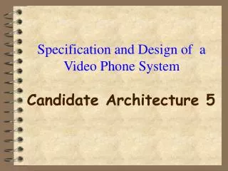
VIDEO PHONE SYSTEM Candidate Architecture 3
Block Diagram of Video Phone System (Top Level) Clock and timing Audio processor Flash memory Camera LCD Audio sub-system Audio controller Flash Memory Video Processor Main controller Video controller Speaker Microphone Audio processor Main control sub-system Video sub-system Video I/O Audio I/O Phone sub-system Audio and Video Data I/O port (Modem)
Video Phone System (Feasibility Study) Video unit: •Digital video processor: DSP56651 (Motorola, $15 each); 16-bit DSP, 70 MIPS •Video controller: MC68HC16S2 (Motorola, $8 each). • Flash memory: HY29F040 (Hyundai, 4MB module, $12 each). • Digital camera: Loitech 961121 (Logitech, $30 each). • Liquid crystal display: TX26D80VC1CAA (Hitachi,10.4” TFT, $100 each). Telephone: •Regular phone unit: $8 each.
Video Phone System (Feasibility Study) Audio unit: •Digital audio processor: CS4912 (Cirrus Logic, $7 each); 16-bit DSP, RAM for program and data. • Audio controller: CS4281 (Cirrus Logic, $4 each). • Flash memory: HY29F040 (Hyundai, 4MB module, $12 each). Main controller and other components: • Main controller: MC68HC16Z2 (Motorola, $10 each). • Modem: WINCOMM56(Jaton Corp. 56K, $15 each).
Video Phone System (Cost and Competition) • COST: A) Audio processor and controller = $ 11 B) Video processor and controller = $ 23 C) Memory(4 MB audio, 4MB video) = $ 24 D) Telephone = $ 8 E) Digital camera = $ 30 F) Modem = $ 15 G) LCD display = $ 100 H) Main microcontroller = $ 10 I) Design cost (assuming 100,000 sold) = $ 27 Total: = $ 250 • MSRP: Price: (40% gross profit margin) = $ 350 • Competition: Standalone: (record motion pictures)>$1,000 TV-based: (need TV) around $800 PC-based: (need PC, slow) around $100
Block Diagram of Video Phone System (Top Level) Clock and timing Audio processor Flash memory Camera LCD Audio sub-system Audio controller Flash Memory Video Processor Main controller Video controller Speaker Microphone Audio processor Main control sub-system Video sub-system Video I/O Audio I/O Phone sub-system Audio and Video Data I/O port (Modem)
The Elements of a Speech Coding System Filter A/D Analysis Quantizer Coder Quantizer-1 Decoder Modem Channel Modem Storage Filter D/A Synthesis
Block Diagram of a LPC Coder Frame interval Coded pitch and voicing Pitch detector Coder Pre-emphasis Multi- plexor Coded LPC coeff’s LPC quantizer and coder Digital channel Correlation computation Window LPC analysis Coder Coded gain LPC filter order Frame interval Widow length
Block Diagram of LPC Decoder Excitation model Pulse generator De- emphasis Demulti- plexor Gain Noise generator Linear predictor LPC coeff
Waveform of Output Signal Input file size: 336KB; compressed file size 7KB; compression ratio is 48:1. Decompressed file size: 336KB.
Block Diagram of Video Phone System (Top Level) Clock and timing Audio processor Flash memory Camera LCD Audio sub-system Audio controller Flash Memory Video Processor Main controller Video controller Speaker Microphone Audio processor Main control sub-system Video sub-system Video I/O Audio I/O Phone sub-system Audio and Video Data I/O port (Modem)
State Diagram of Audio Unit (top level) Standby (Idle) Reset Stop button pickup hangup hangup ring=4 Respondtosystembutton Phonecomm Respondtoline
State Diagram of Audio Unit (Respondtosystembutton subsystem) stopbutton Standby (Idle) Reset playbutton Handleplay fwdbutton rewbutton Handlefwd hearannbutton Handlerew recannbutton Handlehearann playmsgbutton Handlerecann deletemsgbutton Handleplaymsg Handledeletemsg
State Diagram of Audio Unit (Respondtoline subsystem) Standby (Idle) Reset hangup ring=4 hangup Respondtoline hangup hangup Initcomm Recordmessage Playannoncement remotebutton Remotecontrol passwd=‘0’ passwd=‘1’ Respondtoremotebutton Checkcode
Simulation Result for Audio Unit (Phonecomm and Respondtosystembutton subsystems) sreg State Idle 0000 Phone 0001 Handle_play 0111 Handle_fwd 1000 Handle_rew 1001
Simulation Result for Audio Unit (Respondtoline subsystem) sreg State Initcomm 0010 Playann 0011 Recmsg 0100 Check_code 0101 Respondtocmds 0110
Conclusions • Cost/performance reduction approaches: Hardware/software co-design; Off-the-shelf components (small quantity); In-house design and fabrication of chips (large quantity). • Competing with existing products: Aiming at GSTN (analog phone line) market; Cheaper than existing standalone units; More convenient than TV-based or PC-based units.