Download
1 / 36
360 likes | 516 Views
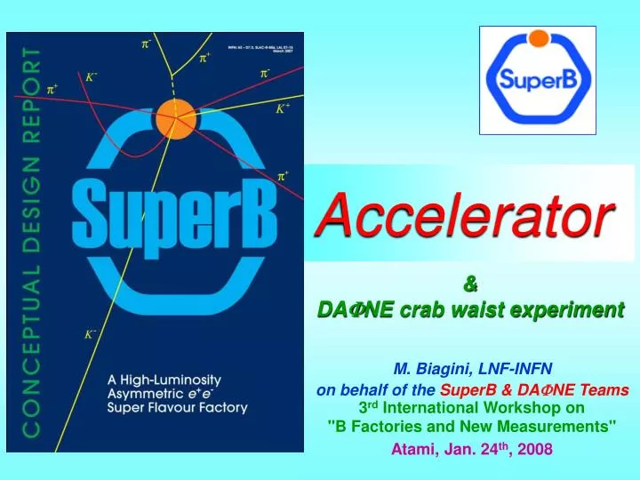
Accelerator. M. Biagini, LNF-INFN on behalf of the SuperB & DA F NE Teams 3 rd International Workshop on "B Factories and New Measurements" Atami, Jan. 24 th , 2008. & DA F NE crab waist experiment. Outline. How to increase Luminosity? The new collision scheme

E N D
Accelerator M. Biagini, LNF-INFN on behalf of the SuperB & DAFNE Teams 3rd International Workshop on "B Factories and New Measurements" Atami, Jan. 24th, 2008 & DAFNE crab waist experiment
Outline • How to increase Luminosity? • The new collision scheme • SuperB beam-beam simulations • SuperB parameters, layout, lattice • DAFNE upgrade with new scheme • DAFNE commissioning status • Conclusions
SuperB Accelerator Contributors • M. E. Biagini, M. Boscolo, A. Drago, S. Guiducci, M. Preger, P. Raimondi, S. Tomassini, • C. Vaccarezza, M. Zobov (INFN/LNF, Italy) • Y. Cai, A. Fisher, S. Heifets, A. Novokhatski, M.T. Pivi, J. Seeman, M. Sullivan, U. Wienands (SLAC, US) • T. Agoh, K. Ohmi, Y. Onhishi (KEK, Japan) • I. Koop, S. Nikitin, E. Levichev, P. Piminov, D. Shatilov (BINP, Russia) • Wolski (Liverpool University, UK) • M. Venturini (LBNL, US) • S. Bettoni (CERN, Geneva) • A. Variola(LAL/Orsay, France) • E. Paoloni (Pisa University, Italy)
Increase beam currents Decrease by* Decrease bunch length HOM in beam pipe overheating, instabilities, power costs Detector backgrounds increase Chromaticity increase smaller dinamic aperture RF voltage increase costs, instabilities How to increase L ? But... “Brute force” method
Hourglass effect To squeeze the vertical beam dimensions, and increase L, by at IP must be decreased. This is efficient only if at the same time the bunch length is shortened to »by value, or particles in the head and tail of the bunch will see a larger by. by* Bunch length
Ultra-low emittance (ILC-DR like) Very small b*at IP Large crossing angle “Crab Waist”scheme Small collision area Lower b ispossible NO parasitic crossings NO synchro-betatron resonances due to crossing angle A new idea for L increase P. Raimondi’s: to focus more the beams at IP and have a “large” crossing angle large Piwinski angle Test at DAFNE now !!!
Large crossing angle, small x-size Overlap region sx sz Y sz y waist can be moved along z with a sextupole on both sides of IP at proper phase “Crab Waist” sx 1) Head-on, Short bunches 2) Large crossing angle, long bunches Vertical waist has to be a function of x: Z = 0 for particles at –sx(- sx/2q at low current) Z = sx/q for particles at + sx(sx/2q at low current) (1) and (2) have same Luminosity, but (2) has longer bunches and smaller sx Large Piwinski angle: F = tg(q)sz/sx
Higher luminosity with same currents and bunch length: Beam instabilities are less severe Manageable HOM heating No coherent synchrotron radiation of short bunches No excessive power consumption Lower beam-beam tune shifts Relatively easier to make small sxw.r.t. short sz Parasitic collisions becomes negligible due to higher crossing angle and smaller sx ... and ...
Here is Luminosity gain IP beam distributions for KEKB Beams are focused in the vertical plane100 times morethan in the present factories, thanks to: - small emittances - small beta functions - larger crossing angle Tune shifts and longitudinal overlap are greatly reduced IP beam distributions forSuperB
Luminosity and blow-up vs current M. Zobov
Luminosity vs tunes scan P. Raimondi, D. Shatilov, M. Zobov • Individual contours differ by 10% in luminosity • Design luminosity can be obtained over a wide tune area (horizontal axis - nx from 0.5 to 0.65; vertical axis – ny from 0.5 to 0.65)
Transparency condition • Due to the large crossing angle, new conditions are possible, different from asymmetric currents, for having equal tune shifts with asymmetric energies • LERandHERbeams can have different emittances and b* and equal currents Present B-factories SuperB
e- e+ LER sz HER sz • LER beam: • sees a shorter overlap region, • (4/7 of the HER one) • has a smaller by*, easier to achieve in the FF w.r.t. HER • has larger emittance: better for Touschek lifetime, and tolerance for LER instabilities
SuperB parameters (1) • Present parameter set based on ILCDR-like parameters • Same DR emittances • Same DR bunch length • 1.5 times DR bunch charges • Same ILC-IP betas • Crossing angle and “crab waist” to maximize luminosity and minimize blowup • Presently under test at DAFNE • Use PEP-KEK DR damping time 19 ms • No “emittance” wigglers used in Phase 1
SuperB parameters (2) • ILC/FFTB like Final Focus • Design based on recycling all PEP-II hardware, Bends, Quads and Sexts, and RF system • Corresponds to a lot of money ! • Maximize Luminosity keeping low wall power: • Total power: 17 MW, lower than PEP-II • Simulations performed in many labs and with different codes: • LNF,BINP,KEK,LAL,CERN
SuperB Parameters (Phase 1) Transparency conditions
Ring Layout Total length ~1800 m Length 20 m Length 280 m HER No polarization section here
Final Focus • Crossing angle to 2*25 mrad, L*=0.4 m • Local chromaticity correction • Horiz.beam separation at QD0: 2 cm, about 180 sx • A possible solution with a septum QD0, to avoid the high background rate in the detector which would be produced by the over-bend off-energy particles if a dipolar component is present, is being studied. • In the novel design, based on SC “helical-type” windings, the windings generate pure quadrupole field as a superposition of the inner field of the surrounding coil and of the outer fringe field of the neighbor one (Bettoni, Paoloni). Overall thickness ~ 8mm, leaving about 60 sx of beam stay-clear.
IP layout M.Sullivan
Example of QD0 design S. Bettoni, E. Paoloni Work in progress
Polarization • Polarization of one beam is included in SuperB • Either energy beam could be the polarized one. • The LER would be less expensive. • Long polarization times and short beam lifetimes indicate a need to inject polarized electrons in the vertical plane • There are several possible IP spin rotators • Solenoids look better at present • Expected longitudinal polarization at the IP of about 87%(inj) x 97%(ring)=85%(effective) J. Seeman, International Review Committee Meeting, LNF, Nov.07
DAFNE upgrade with “crab waist” DAFNEUpgrade Team D. Alesini, M. E. Biagini, C. Biscari, R. Boni, M. Boscolo, F. Bossi, B. Buonomo, A. Clozza, G. Delle Monache, T. Demma, E. Di Pasquale, G. Di Pirro, A. Drago, A. Gallo, A. Ghigo, S. Guiducci, C. Ligi, F. Marcellini, G. Mazzitelli, C. Milardi, F. Murtas, L. Pellegrino, M. Preger, L. Quintieri, P. Raimondi, R. Ricci, U. Rotundo, C. Sanelli, M. Serio, F. Sgamma, B. Spataro, A. Stecchi, A. Stella, S. Tomassini, C. Vaccarezza, M. Zobov (INFN/LNF) I. Koop, E. Levichev, P. Piminov, D. Shatilov, V. Smaluk (BINP) S. Bettoni (CERN, Geneva) K. Ohmi (KEK) N. Arnaud, D. Breton, P. Roudeau, A. Stocchi, A. Variola, B. F. Viaud (LAL/Orsay) M. Esposito (Rome1 University) E. Paoloni (Pisa University) P. Branchini (Roma3 University) M. Schioppa (INFN Gruppo di Cosenza) P. Valente (INFN-Roma)
DAFNE Upgrade Parameters Larger Piwinski angle Lower vertical beta Already achieved
DAFNE test expected results (BBI code by K. Hirata) • The upgrade of DAFNE run the new collision scheme will allow for peak luminosities of 1033 cm-2 s-1 • The use of “crab waist” sextupoles will add a bonus for suppression of dangerous resonances • Brand new IRs layout and equipments have been designed, constructed and installed • This test will have the fundamental function of validating the simulation Luminosity vs beam current
Luminosity vs tunes scan M. Zobov Crab On 0.6/q Crab Off
Strong-Strong Simulations Single Bunch Luminosity Crab Waist On Crab Waist On Crab Waist Off tdamping = 30.000 turns tdamping = 110.000 turns x110 bunches = 1033 cm-2 s-1 (K. Ohmi, BBSS Simulations)
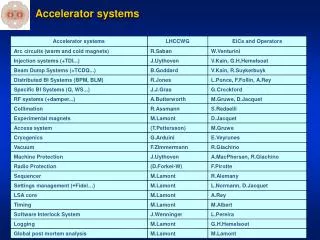
SIDDHARTA Setup SIDDHARTA QF1 Kaon monitor Bhabha monitor Lead shield g monitor
Commissioning status (1) • Rings closed end November • First beams beginning of December • Some BPMs problems due to new RF frequency solved • Maximum currents up to now 700/400 mA (e-/e+) • Found pm quads lower gradient (2%) than expected rematched optics • Coupling ~ 0.4/1.1% (e-/e+) • Crab waist optics implemented, phase between sextupoles OK
Commissioning status (2) • Measured b-functions and dispersion in agreement with model • Collisions started at 200 on 200 mA (e-/e+), 60 bunches • Measured vertical IP size: Sy = 8.1 mm • Tuning of all subsystems in progress • SIDDHARTA Detector will be installed first week of February Beam currents in 24 h
Conclusions (1) • New large Piwinski angle scheme in SuperB will allow for peak luminosity ³ 1036 cm-2 s-1well beyond the current state-of-the-art,without a significant increase in beam currents or shorter bunch lengths • Use of “crab waist” sextupoles will add a bonus for suppression of dangerous resonances • Expected luminosity increase due to “Crab Waist” is: a) a factor of 3, at least, for the DAFNE upgrade b) about 2 orders of magnitude for the SuperB project (with respect to the existing B-Factories) • The principle is being tested at DANE
There is an international interest and participation inSuperB A CDR is being reviewed by theInternational Review Committee In case of positive answer a TDR will be ready by 2010 Next issues are:site, money, people Conclusions (2) • Upgraded DAFNEis in commissioning phase • Collisions at low current started • Results are expected very soon