Download
1 / 22
770 likes | 1.85k Views
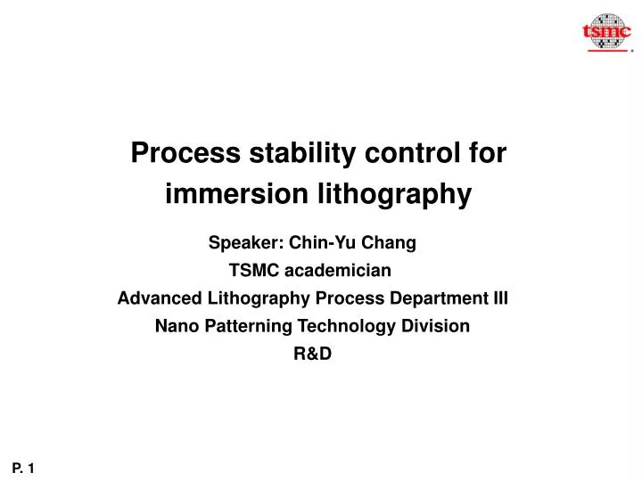
Process stability control for immersion lithography. Speaker : Chin-Yu Chang TSMC academician Advanced Lithography Process Department III Nano Patterning Technology Division R&D. Outline. 1. Immersion tool 2. Immersion material 3. Immersion process. Hardware Clean parts No trash cans

E N D
Process stability control for immersion lithography Speaker: Chin-Yu Chang TSMC academician Advanced Lithography Process Department III Nano Patterning Technology Division R&D
Outline 1. Immersion tool 2. Immersion material 3. Immersion process
Hardware Clean parts No trash cans Water flow Soon refresh rate Flow direction Laminar flow, no dead zone Stage movement Optimized scan/step speed, accel Optimized routing Scanner Defect Stability Control lens UPW inlet UPW outlet water wafer Stage • Surface treatment • Hydrophobic or hydrophilic • Meniscus stability • Less water loss • Surface material endurance • Facility(UPW, Air, CO2) • Supply stability • Extreme clean material • Filtration
Automatic self-cleanKeep system clean always Triggered by wafer # or time Liquid particle Surfactant-ASurfactant-BSurfactant-C… Anion, cation, TOC, metal… Immersion chamber monitor SPC control, real time monitorTrace wafer cleannessMonitor chamber cleanness in-line chemical cleaning Contaminant removalSurfactant via recipe control Functionality for Tool Maintenance UPW outlet UPW inlet lens water wafer Stage
How to Correlate Defect to System 6250-193, SPIE 2007, FJ Liang Robust tooling for the monitor, analysis, simulation and prediction of defect behavior
Key module Coater, developer and soaking units Configuration Customized hardware (tube, nozzle, arm, cup, exhaust…) Optimized unit recipe & wafer flow to improve defect Innovative treatment units Maintenance Environment control Advanced PM skills to remain baseline Exploratory methodology to qualify module performance Requirement for Track Defect Reduction
Tool Stability Control From defectivity point of view
Developer Strategy and Challenge Spin dry Similar contact angle between surface and sidewall PSM/ topcoat • High surface contact angle difference between surface and pattern side wall BIM process • Treatment: • . Treatment process
CH Developer Strategy and Challenge Spin dry
Implant Layer Scum Reduction Modified PR NPR Treatment Good profile, CDU No scum, poison issue Precise implant control Good top view profile No scum Advantage Disadvantage New process Substrate damage? COO Scum, poison issue Poor optical intensity in small trench Chemical diffuse difficulty DBARC iso dense bias Poor undercut profile PR maturity
Immersion defect analysis – the interaction between tool, material and process Lens Resist process Contamination source: EBR, film stack, resist leaching Pattern defect Source: IH, stage IH IH wafer stage Immersion hood Contamination source: resist, tool, dry/wet interface Clean strategy: mechanical or chemical clean Lens Contamination source: Leaching PAG, Particle Clean strategy: chemical clean stage Contamination source: WS, IH, resist Clean strategy: mechanical or chemical clean
Immersion Process- EBR Process EBR Process OM picture SEM picture defect OM wafer edge SEM Wafer edge PR BARC Conv. TARC BARC New PR Stress Adhesion Swelling Hydrophobic/philic Film stack: Film peeling
Lens Cleaning Chemical Performance Sample 1 Sample 2
Pre Scanner Cleaning 1 Cleaning 2 0.65 Amp Mega sonic 112 34 641 9 0.9 Amp Mega sonic 205 247 645 3 Particle remove rate vs. mega sonic power RR. ampere
Particle accumulation and cleaning Immersion head Water control apparatus lens Background facility Lens 1cm out DI in fluid in fluid out fluid out Lens fluid in
Water drop PR layer Wafer Watermark defect mechanism water drop residue after immersion exposure Immersion head Wafer Leaching from resist or contamination from air influence the CAR(chemical amplify reaction) Stage movement direction
Pattern collapse, defect and its solutions • BARC • Conventional: • Only consider the n,k value • Our approach • Adhesion improvement -- Tail structure, Porous structure • Surface condition improvement -- Leaving group structure, polarity switchable group Developer Conventional Surfactant rinse Our approach New surfactant for collapse and defect improvement F h w • Resist • Conventional: • Improve resist rigidity • Our approach • Change the surface condition to decrease the swelling and increase surface hydrophobic. • Special formulation to decrease the capillary torque force D F=6Stcos/D(AR)2 AR: aspect ratio : contact angle D: space width
Pattern collapse and LWR TMAH DI water rinse Spin- dry Chemical treatment