Download
1 / 54
540 likes | 552 Views
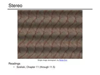
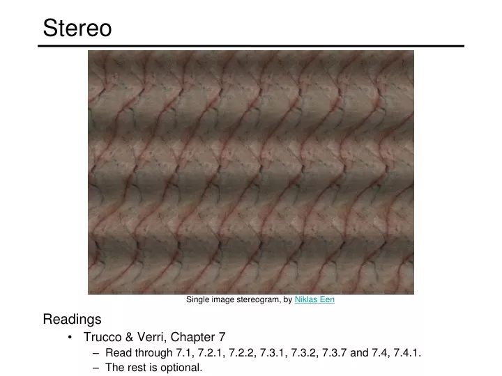
Stereo. Readings Trucco & Verri, Chapter 7 Read through 7.1, 7.2.1, 7.2.2, 7.3.1, 7.3.2, 7.3.7 and 7.4, 7.4.1. The rest is optional. Single image stereogram, by Niklas Een. Public Library, Stereoscopic Looking Room, Chicago, by Phillips, 1923. Teesta suspension bridge-Darjeeling, India.

E N D
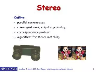
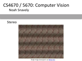
Stereo • Readings • Trucco & Verri, Chapter 7 • Read through 7.1, 7.2.1, 7.2.2, 7.3.1, 7.3.2, 7.3.7 and 7.4, 7.4.1. • The rest is optional. Single image stereogram, by Niklas Een
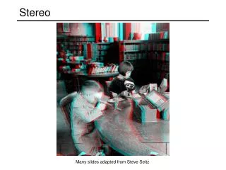
Public Library, Stereoscopic Looking Room, Chicago, by Phillips, 1923
Woman getting eye exam during immigration procedure at Ellis Island, c. 1905 - 1920, UCR Museum of Phography
Mark Twain at Pool Table", no date, UCR Museum of Photography
Stereo scene point image plane optical center
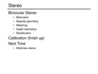
Stereo • Basic Principle: Triangulation • Gives reconstruction as intersection of two rays • Requires • camera pose (calibration) • point correspondence
epipolar line epipolar line epipolar plane Stereo correspondence • Determine Pixel Correspondence • Pairs of points that correspond to same scene point • Epipolar Constraint • Reduces correspondence problem to 1D search along conjugateepipolar lines • Java demo: http://www.ai.sri.com/~luong/research/Meta3DViewer/EpipolarGeo.html
epipolar line epipolar plane Fundamental matrix • This epipolar geometry of two views is described by a Very Special 3x3 matrix , called the fundamental matrix • maps (homogeneous) points in image 1 to lines in image 2! • The epipolar line (in image 2) of point p is: • Epipolar constraint on corresponding points: epipolar line (projection of ray) 0 Image 1 Image 2
Fundamental matrix – uncalibrated case 0 : intrinsics of camera 2 : intrinsics of camera 1 : rotation of image 2 w.r.t. camera 1 the Fundamental matrix
Cross-product as linear operator • Useful fact: Cross product with a vector t can be represented as multiplication with a (skew-symmetric) 3x3 matrix
Fundamental matrix – calibrated case 0 : ray through p in camera 1’s (and world) coordinate system : ray through q in camera 2’s coordinate system { the Essential matrix
Properties of the Fundamental Matrix • is the epipolar line associated with • is the epipolar line associated with • and • is rank 2 • How many parameters does F have? T
Stereo image rectification • reproject image planes onto a common • plane parallel to the line between optical centers • pixel motion is horizontal after this transformation • two homographies (3x3 transform), one for each input image reprojection • C. Loop and Z. Zhang. Computing Rectifying Homographies for Stereo Vision. IEEE Conf. Computer Vision and Pattern Recognition, 1999.
Estimating F • If we don’t know K1, K2, R, or t, can we estimate F for two images? • Yes, given enough correspondences. We’ll see soon…
Stereo Matching • Given a pixel in the left image, how to find its match? • Assume the photos have been rectified
For each epipolar line For each pixel in the left image • Improvement: match windows • This should look familar... Your basic stereo algorithm • compare with every pixel on same epipolar line in right image • pick pixel with minimum match cost
W = 3 W = 20 Window size • Smaller window • Larger window Effect of window size
Stereo results • Data from University of Tsukuba • Similar results on other images without ground truth Scene Ground truth
Results with window search Window-based matching (best window size) Ground truth
Better methods exist... State of the art method Boykov et al., Fast Approximate Energy Minimization via Graph Cuts, International Conference on Computer Vision, September 1999. Ground truth For the latest and greatest: http://www.middlebury.edu/stereo/
Stereo as energy minimization • What defines a good stereo correspondence? • Match quality • Want each pixel to find a good match in the other image • Smoothness • If two pixels are adjacent, they should (usually) move about the same amount
Stereo as energy minimization • Find disparity map d that minimizes an energy function • Simple pixel / window matching = SSD distance between windows I(x, y) and J(x + d(x,y), y)
Stereo as energy minimization I(x, y) J(x, y) y = 141 d x C(x, y, d); the disparity space image (DSI)
Stereo as energy minimization y = 141 d x Simple pixel / window matching: choose the minimum of each column in the DSI independently:
Stereo as energy minimization • Better objective function { { smoothness cost match cost • Want each pixel to find a good match in the other image • Adjacent pixels should (usually) move about the same amount
Stereo as energy minimization match cost: smoothness cost: : set of neighboring pixels 4-connected neighborhood 8-connected neighborhood
Smoothness cost How do we choose V? L1 distance “Potts model”
Dynamic programming • Can minimize this independently per scanline using dynamic programming (DP) : minimum cost of solution such that d(x,y) = d
Dynamic programming • Finds “smooth” path through DPI from left to right y = 141 d x
Dynamic programming • Can we apply this trick in 2D as well? • No: dx,y-1 and dx-1,y may depend on different values of dx-1,y-1 Slide credit: D. Huttenlocher
Stereo as global optimization • Expressing this mathematically • Match quality • Want each pixel to find a good match in the other image • Smoothness • If two pixels are adjacent, they should (usually) move about the same amount • We want to minimize sum of these two cost terms • This is a special type of cost function known as an MRF (Markov Random Field) • Effective and fast algorithms have been recently developed: • Graph cuts, belief propagation…. • for more details (and code): http://vision.middlebury.edu/MRF/
Middlebury Stereo Evaluation • http://vision.middlebury.edu/stereo/ 38
X z x x’ f f baseline C C’ Depth from disparity
Real-time stereo • Used for robot navigation (and other tasks) • Several software-based real-time stereo techniques have been developed (most based on simple discrete search) Nomad robot searches for meteorites in Antartica http://www.frc.ri.cmu.edu/projects/meteorobot/index.html
Stereo reconstruction pipeline • Steps • Calibrate cameras • Rectify images • Compute disparity • Estimate depth • Camera calibration errors • Poor image resolution • Occlusions • Violations of brightness constancy (specular reflections) • Large motions • Low-contrast image regions What will cause errors?
camera 1 projector Active stereo with structured light • Project “structured” light patterns onto the object • simplifies the correspondence problem • can remove one of the cameras (replace with projector) http://www.youtube.com/watch?v=7QrnwoO1-8A Microsoft’s Kinect
Laser scanning • Optical triangulation • Project a single stripe of laser light • Scan it across the surface of the object • This is a very precise version of structured light scanning Digital Michelangelo Project http://graphics.stanford.edu/projects/mich/
Laser scanned models The Digital Michelangelo Project, Levoy et al.
Laser scanned models The Digital Michelangelo Project, Levoy et al.
Laser scanned models The Digital Michelangelo Project, Levoy et al.
Laser scanned models The Digital Michelangelo Project, Levoy et al.
Laser scanned models The Digital Michelangelo Project, Levoy et al.
Estimating F • If we don’t know K1, K2, R, or t, can we estimate F for two images? • Yes, given enough correspondences
Estimating F – 8-point algorithm • The fundamental matrix F is defined by for any pair of matches x and x’ in two images. • Let x=(u,v,1)T and x’=(u’,v’,1)T, each match gives a linear equation