Download
1 / 43
430 likes | 564 Views
Stereo. Many slides adapted from Steve Seitz. Binocular stereo. Given a calibrated binocular stereo pair, fuse it to produce a depth image. Where does the depth information come from?. Binocular stereo. Given a calibrated binocular stereo pair, fuse it to produce a depth image. image 1.

E N D
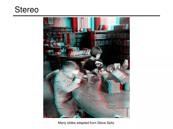
Stereo Many slides adapted from Steve Seitz
Binocular stereo • Given a calibrated binocular stereo pair, fuse it to produce a depth image Where does the depth information come from?
Binocular stereo • Given a calibrated binocular stereo pair, fuse it to produce a depth image image 1 image 2 Dense depth map
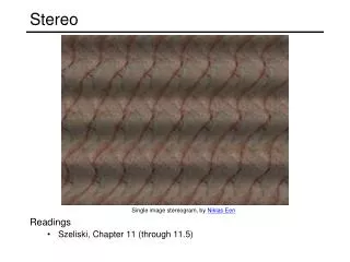
Binocular stereo • Given a calibrated binocular stereo pair, fuse it to produce a depth image • Humans can do it Stereograms: Invented by Sir Charles Wheatstone, 1838
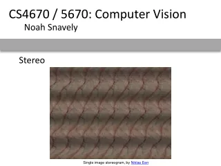
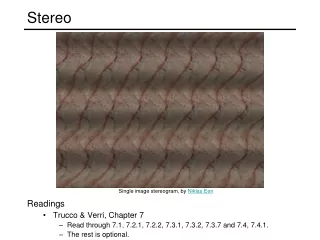
Binocular stereo • Given a calibrated binocular stereo pair, fuse it to produce a depth image • Humans can do it Autostereograms: www.magiceye.com
Binocular stereo • Given a calibrated binocular stereo pair, fuse it to produce a depth image • Humans can do it Autostereograms: www.magiceye.com
Basic stereo matching algorithm • For each pixel in the first image • Find corresponding epipolar line in the right image • Examine all pixels on the epipolar line and pick the best match • Triangulate the matches to get depth information • Simplest case: epipolar lines are corresponding scanlines • When does this happen?
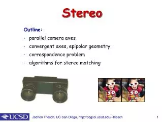
Simplest Case: Parallel images • Image planes of cameras are parallel to each other and to the baseline • Camera centers are at same height • Focal lengths are the same
Simplest Case: Parallel images • Image planes of cameras are parallel to each other and to the baseline • Camera centers are at same height • Focal lengths are the same • Then, epipolar lines fall along the horizontal scan lines of the images
Essential matrix for parallel images Epipolar constraint: R = It = (T, 0, 0) x x’ t The y-coordinates of corresponding points are the same!
X z x x’ f f BaselineB O O’ Depth from disparity Disparity is inversely proportional to depth!
Stereo image rectification • reproject image planes onto a common • plane parallel to the line between optical centers • pixel motion is horizontal after this transformation • two homographies (3x3 transform), one for each input image reprojection • C. Loop and Z. Zhang. Computing Rectifying Homographies for Stereo Vision. IEEE Conf. Computer Vision and Pattern Recognition, 1999.
Correspondence search • Slide a window along the right scanline and compare contents of that window with the reference window in the left image • Matching cost: SSD or normalized correlation Left Right scanline Matching cost disparity
Correspondence search Left Right scanline SSD
Correspondence search Left Right scanline Norm. corr
Basic stereo matching algorithm • If necessary, rectify the two stereo images to transform epipolar lines into scanlines • For each pixel x in the first image • Find corresponding epipolarscanline in the right image • Examine all pixels on the scanline and pick the best match x’ • Compute disparity x-x’ and set depth(x) = B*f/(x-x’)
Failures of correspondence search Occlusions, repetition Textureless surfaces Non-Lambertian surfaces, specularities
Effect of window size • Smaller window • More detail • More noise • Larger window • Smoother disparity maps • Less detail W = 3 W = 20
Results with window search Data Window-based matching Ground truth
Better methods exist... Ground truth Graph cuts • Y. Boykov, O. Veksler, and R. Zabih, Fast Approximate Energy Minimization via Graph Cuts, PAMI 2001 • For the latest and greatest: http://www.middlebury.edu/stereo/
How can we improve window-based matching? • The similarity constraint is local (each reference window is matched independently) • Need to enforce non-local correspondence constraints
Non-local constraints • Uniqueness • For any point in one image, there should be at most one matching point in the other image
Non-local constraints • Uniqueness • For any point in one image, there should be at most one matching point in the other image • Ordering • Corresponding points should be in the same order in both views
Non-local constraints • Uniqueness • For any point in one image, there should be at most one matching point in the other image • Ordering • Corresponding points should be in the same order in both views Ordering constraint doesn’t hold
Non-local constraints • Uniqueness • For any point in one image, there should be at most one matching point in the other image • Ordering • Corresponding points should be in the same order in both views • Smoothness • We expect disparity values to change slowly (for the most part)
Left image Right image Scanline stereo • Try to coherently match pixels on the entire scanline • Different scanlines are still optimized independently
Left image Right image Right occlusion q Left occlusion t s p “Shortest paths” for scan-line stereo correspondence • Can be implemented with dynamic programming • Ohta & Kanade ’85, Cox et al. ‘96 Slide credit: Y. Boykov
Coherent stereo on 2D grid • Scanline stereo generates streaking artifacts • Can’t use dynamic programming to find spatially coherent disparities/ correspondences on a 2D grid
Stereo matching as energy minimization • Energy functions of this form can be minimized using graph cuts I2 D I1 W1(i) W2(i+D(i)) D(i) data term smoothness term • Y. Boykov, O. Veksler, and R. Zabih, Fast Approximate Energy Minimization via Graph Cuts, PAMI 2001
camera projector Active stereo with structured light • Project “structured” light patterns onto the object • Simplifies the correspondence problem • Allows us to use only one camera L. Zhang, B. Curless, and S. M. Seitz. Rapid Shape Acquisition Using Color Structured Light and Multi-pass Dynamic Programming.3DPVT 2002
Active stereo with structured light L. Zhang, B. Curless, and S. M. Seitz. Rapid Shape Acquisition Using Color Structured Light and Multi-pass Dynamic Programming.3DPVT 2002
Active stereo with structured light http://en.wikipedia.org/wiki/Structured-light_3D_scanner
Kinect: Structured infrared light http://bbzippo.wordpress.com/2010/11/28/kinect-in-infrared/
Laser scanning • Optical triangulation • Project a single stripe of laser light • Scan it across the surface of the object • This is a very precise version of structured light scanning • Digital Michelangelo Project • Levoy et al. • http://graphics.stanford.edu/projects/mich/ Source: S. Seitz
Laser scanned models • The Digital Michelangelo Project, Levoy et al. Source: S. Seitz
Laser scanned models • The Digital Michelangelo Project, Levoy et al. Source: S. Seitz
Laser scanned models • The Digital Michelangelo Project, Levoy et al. Source: S. Seitz
Laser scanned models • The Digital Michelangelo Project, Levoy et al. Source: S. Seitz
Laser scanned models 1.0 mm resolution (56 million triangles) • The Digital Michelangelo Project, Levoy et al. Source: S. Seitz
Aligning range images • A single range scan is not sufficient to describe a complex surface • Need techniques to register multiple range images B. Curless and M. Levoy, A Volumetric Method for Building Complex Models from Range Images, SIGGRAPH 1996
Aligning range images • A single range scan is not sufficient to describe a complex surface • Need techniques to register multiple range images • … which brings us to multi-view stereo