Download
1 / 22
230 likes | 379 Views
Plasma Shape Reproduction of Spherical Tokamak by Using CCS Method. F. W ANG * and K. N AKAMURA AEES, Kyushu University O. MITARAI Kyushu Tokai University K. KURIHARA, Y. KAWAMATA and M. SUEOKA Directorates of Fusion Energy Research, Japan Atomic Energy Agency. Outline.

E N D
Plasma Shape Reproduction of Spherical Tokamak by Using CCS Method F. WANG * and K. NAKAMURA AEES, Kyushu University O. MITARAI Kyushu Tokai University K. KURIHARA,Y. KAWAMATA and M. SUEOKA Directorates of Fusion Energy Research, Japan Atomic Energy Agency
Outline • 1. Introduction • 2. Motivations • 3. Principle of CCS method • 4. Calculation on TRIAM-1M • 5. Calculation on CPD • 6. Summary
1. Introduction Spherical Tokamak (ST) a R Small Aspect Ratio (A=R/a) < 2 Conventional Tokamak High natural elongation High natural triangularity Equilibrium and stability properties are much different with the conventional Tokamaks Spherical Tokamak
CPD (Compact PWI Experimental Device) RIAM, Kyushu University • Plasma major radius: 0.3 m • Plasma minor radius: 0.2 m • Toroidal field: 0.3 T @ R = 0.25 m • Operation period: 1.00 sec for Bt = 0.3 T • Operation cycle: 5 min • Plasma current: 150 kA Main parameters of CPD:
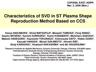
Cauchy-Condition Surface Method • Shape reproduction is important for plasma control in a tokamak, especially for non-circular and triangular plasmas. • Cauchy-Condition Surface (CCS) method * is a numerical approach to reproduce plasma shape. • The CCS method can reproduce plasma shape with high precision corresponding to the number and types of available sensors. 2) The CCS method can identify plasma current with an error of less than 2% 3) The CCS position and shape are insensitive to reproduction accuracy. This is advantageous in the application to the real-time plasma control. Magnetic Sensors Plasma Shape and Position Poloidal Field Coils * The CCS method was proposed by Dr. K. Kurihara.
CCS FCAFEA Compared with FCA, CCS method has less difference with FEA method. * * K. Kurihara, Fusion Engineering and Design51-52 (2000) 1049–1057.
2. Motivations • As for the spherical tokamak, the aspect ratio is much smaller than normal tokamaks, so the shape reproduction precision of CCS method under a ST device will be studied, and the precision of normal tokamak and spherical tokamak will be compared. • At present there are only flux loops signals in CPD spherical tokamak, so the shape reproduction precision of CCS method solely with the measurements of flux loops will be studied. • The CCS method will be used in the real-time plasma shape reproduction and display.
3. Principle of CCS method Cauchy-Condition Surface Dirichlet (Φ) ? Neumann (B) ? CCS Magnetic Measurements Cauchy-Condition Surface Dirichlet (Φ) Neumann (B) Actual Plasma Surface Flux Distribution Plasma Boundary
* (1) Flux Loops CCS && PF Coils (2) Magnetic Probes CCS && PF Coils (3) CCS CCS && PF Coils (4) * K. Kurihara, Fusion Engineering and Design51-52 (2000) 1049–1057.
4. Calculation on TRIAM-1M Equilibrium Code (ECODE) CCS Method Ideal Magnetic Sensors Cauchy-Condition Surface Reproduced Plasma Shape Ideal Plasma Shape Results Comparison (plasma shape, magnetic sensors)
Configuration of TRIAM-1M R: +0.6 ~ +1.1 Z: -0.25 ~ +0.25 PF Coils: 4 Flux Loops: 45 Mesh Size: 100x100 Mesh Precision: 5mm CCS ellipse Center: R=0.84, Z=0.0 Small radius: 0.03m Large radius: 0.04m Discretized Number M: 6
100 100 80 80 60 60 40 40 20 20 20 40 60 80 100 20 40 60 80 100 Comparison of Flux Surface (1) ECODE CCS PF1 PF1 ECODE precision is 0.05% IPF1 = 18KA IP = 100KA
100 100 80 80 60 60 40 40 20 20 20 40 60 80 100 20 40 60 80 100 Comparison of Flux Surface (2) ECODE CCS PF1 PF1 ECODE precision is 0.05% IPF1 = 30KA IP = 100KA
Difference of Flux Loops Value In case of TRIAM-1M, normally the max difference between ideal value and CCS calculation is less than 1%
5. Calculation on CPD Configuration of CPD R: +0.1 ~ +0.8 Z: -0.7 ~ +0.7 PF Coils: 7 Flux Loops: 45 Mesh Size: 140x280 Mesh Precision: 5mm CCS ellipse Center: R=0.28, Z=0.0 Small radius: 0.04m Large radius: 0.06m Discretized Number M: 6
250 250 200 200 150 150 100 100 50 50 20 40 60 80 100 120 140 20 40 60 80 100 120 140 Comparison of Flux Surface (M=6) IPF1 = 30KA IP = 100KA ECODE precision is 0.05% ECODE CCS
Difference of Flux Loops Value (M=6) In case of large elongated and triangular plasma, normally the max difference between ideal value and CCS calculation is large than 5%
250 250 250 200 200 200 150 150 150 100 100 100 50 50 50 20 40 60 80 100 120 140 20 40 60 80 100 120 140 20 40 60 80 100 120 140 Comparison of Flux Surface (M=8,10) ECODE CCS (M=8) CCS (M=10)
6. Summary • The CCS method can reproduce plasma shape of spherical tokamak solely with the measurements of flux loops. • The calculation results of equilibrium code and CCS method werecompared. Normally in case of TRIAM-1M the difference of flux loops value is less than 1%, and in case of CPD by increasing the discretized number of Cauchy-Condition surface, precision can be improved. • FUTURE WORKS: (1) Calculation with experimental data of TRIAM-1M. (2) Optimization of the formula constraint on CCS. (3) Optimization of kind, positions and number of the magnetic sensors. (4) Optimization of calculation for real-time plasma shape reproduction.
THE END THANK YOU!