Download
1 / 24
240 likes | 308 Views
The CBM sensor digitizer. C.Dritsa IKF-Frankfurt, IPHC-Strasbourg (now at JLU Giessen). Outline. Motivation Model requirements Description of the model Important definitions (1) charge generation charge sharing Evaluation Important definitions (2) Comparison with experimental data

E N D
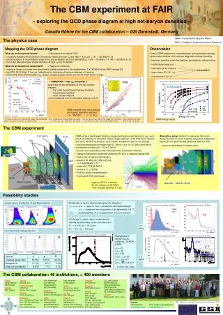
The CBM sensor digitizer C.Dritsa IKF-Frankfurt, IPHC-Strasbourg (now at JLU Giessen) C.Dritsa, St.Odile, 08 September 2011
Outline • Motivation • Model requirements • Description of the model • Important definitions (1) • charge generation • charge sharing • Evaluation • Important definitions (2) • Comparison with experimental data • Outlook C.Dritsa, St.Odile, 08 September 2011
Motivation • Digitizer model developed in order to allow simulating the CBM-MVD. • In collaboration with the IPHC-PICSEL group in Strasbourg and the IKF-MVD group in Frankfurt. • It was inspired by a detector response model developed for the ILC vertex tracker • M. Battaglia, “Response simulation of CMOS pixel sensors for the ILC vertex tracker” , Nuclear Instruments and Methods in Physics Research A 572 (2007) 274–276 C.Dritsa, St.Odile, 08 September 2011
CBM-MVD response model requirements • Realistic simulations allowing to simulate: • Cluster properties: size, shape • pixel size • vary number of ADC channels of the readout • particles impinging with high incident angles • noise, fake hits • Rapid simulation features • simulate collision pile up • delta electrons (of concern in CBM) • fast, allowing high statistics simulations C.Dritsa, St.Odile, 08 September 2011
Spirit of the model • Challenge: • Charge carrier transport process too complex and slow for simulation • Solution: • Parameterization of the sensor response • Use experimental data • GEANT provides only entry and exit coordinates of the particle in the volume • no dE/dx from GEANT C.Dritsa, St.Odile, 08 September 2011
Reference data • Data acquired at CERN/SPS with pions 120 GeV/c • Sensor under test: MIMOSA17 • AMS 0.35 • standard low resistivity epitaxial layer • analogue output (12 bit charge resolution) • 30 µm pixel pitch • Particle incident angles 0-75 degrees (90 degrees is parallel to the sensor plane) C.Dritsa, St.Odile, 08 September 2011
The digitizer C.Dritsa, St.Odile, 08 September 2011
Important definitions (1) Landau Lorentz MPV C.Dritsa, St.Odile, 08 September 2011
Other features • Simulated by random sampling of a distribution following a Gauss law with adjustable µ, σ • mean=0 • σ =15 electrons • Number of ADC bits adjustable • 12 bits • Pixel pitch adjustable • 30 µm C.Dritsa, St.Odile, 08 September 2011
The charge of the cluster is taken by random sampling of the experimental distribution for 25 pixels 0 degrees incident angle The charge distribution among the pixels in the cluster is based on a 2D Lorentz distribution (derived from the 1D) 0 degrees incident angle The model: Input Landau: Accumulated charge on 25 pixels The simulation of inclined particles is derived by this initial parameterization. C.Dritsa, St.Odile, 08 September 2011
Q0, l0 : known lincl: provided by GEANT The model: charge generation C.Dritsa, St.Odile, 08 September 2011
Charge provided by Landau (25 pixels) The trajectory is divided in segments A Lorentz function corresponds to each segment The model: charge distribution Illustration for inclined track C.Dritsa, St.Odile, 08 September 2011
Charge on pixel i x,y-coordinates of segment k The model Lorentz Amplitude Lorentz width L(xk,i,yk,i) Sum over segments (k) x,y-coordinates of pixel i Pixel pitch C.Dritsa, St.Odile, 08 September 2011
Evaluation C.Dritsa, St.Odile, 08 September 2011
Q1 Q1+Q2 Qi<0 (i~N) Q1+Q2+Q3 Q1+Q2+…+Qi Q1 Q2 Q3 Important definitions (2) Accumulated charge plot Q1>Q2>Q3… Accumulated charge (MPV) Q1 Q2 Q3 Qi N 1 2 3 … Number of Pixels The accumulated charge plot describes the charge sharing among the pixels of the cluster: e.g. the seed pixel collects ~30% of the total cluster charge. C.Dritsa, St.Odile, 08 September 2011
Evaluation: MPV of Landau C.Dritsa, St.Odile, 08 September 2011
Evaluation: sigma of Landau C.Dritsa, St.Odile, 08 September 2011
Evaluation Average number of pixels/cluster C.Dritsa, St.Odile, 08 September 2011
Evaluation: shape Simulation Experimental data C.Dritsa, St.Odile, 08 September 2011
Summary and outlook • Digitizer model developed for the CBM-MVD and successfully tested with experimental data. • Model was successfully tested on High-Resistivity sensors (M.Domachowski) • Successfully tested on neutron irradiated sensors (M.Domachowski) • Simulation of MIMOSA-26 data sparcification in process (Q.Li) C.Dritsa, St.Odile, 08 September 2011
Acknowledgments Thanks to: the IPHC-PICSEL group and the IKF-MVD group. In particular: IPHC: J.Baudot, M.Goffe, R.DeMasi, M.Winter IKF: M.Deveaux, M.Domachowski, Q.Li, J.Stroth C.Dritsa, St.Odile, 08 September 2011
Backup C.Dritsa, St.Odile, 08 September 2011
High-Res MAPS: Measurement vs. simulation Melissa Domachowski Simulation of HR-MAPS with the MVD-digitiser: OK Simulation of irradiated MAPS: OK C.Dritsa, St.Odile, 08 September 2011 Simulation of irradiated MAPS in CBM-Root Melissa Domachowski - CBM Collaboration Meeting, Dresden 2011
Particle yields C.Dritsa, St.Odile, 08 September 2011