Download
1 / 29
340 likes | 765 Views
COMP211 Computer Logic Design. Lecture 6. ALU, Shifter, Counter, Shift Register. Prof. Taeweon Suh Computer Science Education Korea University. Comparator. Comparator determines whether two binary numbers are equal or if one is greater or less than the other

E N D
COMP211 Computer Logic Design Lecture 6. ALU, Shifter, Counter, Shift Register Prof. Taeweon Suh Computer Science Education Korea University
Comparator • Comparator determines whether two binary numbers are equal or if one is greater or less than the other • An equality comparator produces a single output indicating whether A is equal to B Example: 4-bit equality comparator
General Comparison • From the subtraction slides, we know that we can do comparison of unsigned numbers and signed numbers by checking flags (N, C, Z, V) after subtraction • N is set to MSB of the result • C is set when there is an end carry-out • Z is set when the result is zero • V is set if signed overflow occurs • Unsigned number comparison • CPU does A – B • If C (carry-out) is 1, then A ≥ B • If C (carry-out) is 0, then A < B • Signed number comparison • CPU does A – B • If (V == N), then A ≥ B • If (V != N), then A < B
Arithmetic Logic Unit (ALU) • ALU is a digital circuit that performs arithmetic and logical operations • ALU is a fundamental building block of CPU (Central Processing Unit) in computers
Basic Shifting • Shift types • Logical (or unsigned) shift • Arithmetic (or signed) shift • Shift directions • Left (multiply by powers of 2) • Right (divide by powers of 2) • Take floor value if the result is not an integer • Floor value of X (or X) is the greatest integer less than or equal to X • 5/2 = 2 • -3/2 = -2 Prof. Sean Lee’s Slide, Georgia Tech
Logical Shift • Logical shift left • MSB: shifted out • LSB: shifted in with a 0 • Examples: • (11001011 << 1) = 10010110 • (11001011 << 3) = 01011000 • Logical shift right • MSB: shifted in with a 0 • LSB: shifted out • Examples: • (11001011 >> 1) = 01100101 • (11001011 >> 3) = 00011001 • Logic shifts are useful to perform multiplication or division of unsigned integer by powers of two • Logical shift right takes floor value if the result is not integer Modified from Prof Sean Lee’s slide, Georgia Tech
Arithmetic Shift • Arithmetic shift left • MSB: shifted out, however, be aware of overflow/underflow • LSB: shifted in with a 0 • Examples: • (1100 <<< 1) = 1000 • (1100 <<< 3) = 0000 (Incorrect!) Underflow • Arithmetic shift right • MSB: Retain its sign bit • LSB: Shifted out • Examples: • (1100 >>> 1) = 1110 (Retain sign bit) • (1100 >>> 3) = 1111 (-4/8 = -1 ) Floor value of -0.5 • Arithmetic shifts can be useful as efficient ways of performing multiplication or division of signed integers by powers of two • Arithmetic shift right takes floor value if the result is not integer Modified from Prof Sean Lee’s slide, Georgia Tech
Overflow/Underflow Examples of Arithmetic Shift 1111 1011 Arithmetic shift right by 1 1111 1101 1111 1011 Arithmetic shift left by 1 1111 0110 1011 1111 (= -65) Arithmetic shift left by 1 (i.e. x2) 0111 1110 (= +126 -130) Underflow ! 0100 0010 (= +66) Arithmetic shift left by 1 (i.e. x2) 1000 0100 (= -124 +132) Overflow ! Prof. Sean Lee’s Slide, Georgia Tech
4-bit Logical Shifter Input A2 A1 A0 A3 S/NS S1 L/R S0 D2 D1 D0 D3 Output Legend S: Shift L: Left NS: No Shift R: Right Prof. Sean Lee’s Slide, Georgia Tech
A3 A0 A2 A1 01 01 01 01 10 10 10 10 11 11 11 11 00 00 00 00 s1 s1 s1 s1 s0 s0 s0 s0 4-to-1 Mux 4-to-1 Mux 4-to-1 Mux 4-to-1 Mux D0 D2 D1 S1 S0 4-bit Logical Shifter using 4:1 Mux Right Shift Left Shift D3 Prof. Sean Lee’s Slide, Georgia Tech
A0 A1 A2 01 01 01 10 10 10 11 11 11 00 00 00 s1 s1 s1 s0 s0 s0 4-to-1 Mux 4-to-1 Mux 4-to-1 Mux D0 D1 D2 S1 S0 4-bit Arithmetic Shifter using 4:1 Mux Right Shift Left Shift A3 01 10 11 00 s1 s0 4-to-1 Mux D3 Prof. Sean Lee’s Slide, Georgia Tech
A1 A0 A2 01 01 01 10 10 10 11 11 11 00 00 00 s1 s1 s1 s0 s0 s0 4-to-1 Mux 4-to-1 Mux 4-to-1 Mux D0 D2 D1 S1 S0 4-bit Arithmetic Shifter using 4:1 Mux Right Shift Overflow/ Underflow Left Shift A3 01 10 11 00 s1 s0 4-to-1 Mux D3 Prof. Sean Lee’s Slide, Georgia Tech
Overflow Underflow Detection A0 A1 A2 01 01 01 10 10 10 11 11 11 00 00 00 s1 s1 s1 s0 s0 s0 4-to-1 Mux 4-to-1 Mux 4-to-1 Mux D2 D0 D1 S1 S0 4-bit Arithmetic Shifter using 4:1 Mux Right Shift Overflow/ Underflow Left Shift A3 01 10 11 00 s1 s0 4-to-1 Mux D3 Prof. Sean Lee’s Slide, Georgia Tech
01 01 01 10 10 10 11 11 11 00 00 00 s1 s1 s1 s0 s0 s0 4-to-1 Mux 4-to-1 Mux 4-to-1 Mux S1 S0 Rotator Input • Rotate right A2 A1 A0 A3 S1 S0 D2 D1 D0 D3 Output A3 A2 A1 A0 01 10 11 00 s1 s0 4-to-1 Mux D3 D2 D1 D0 Prof. Sean Lee’s Slide, Georgia Tech
Barrel Shifter • In many applications, data should be shifted more than one bit position in a single clock cycle • Barrel shifter is one form of combinational circuit that shifts or rotates the input data bits by the number of bits Right Shift Left Shift Prof. Sean Lee’s Slide, Georgia Tech
A3 01 10 11 S2 00 s1 s0 4-to-1 Mux S0 D3 0 2-to-1 Mux 1 S1 s0 4-to-1 Mux s1 01 10 11 00 A2 A1 A0 A3 Barrel Shifter Design w/ Mux (D3) Right Shift Left Shift Replicate and change wiring of the two 4-to-1 Muxes for D2, D1 and D0 Prof. Sean Lee’s Slide, Georgia Tech
Left/Right Barrel Shifter Design Alternative (16-bit) Input Number 16 S3 (S3 S2 S1 S0) specifies the “shift amount” in binary 23 Shifter 16 S2 22 Shifter 16 S1 21 Shifter 16 S0 20 Shifter 16 Prof. Sean Lee’s Slide, Georgia Tech Output Number
Counters • An N-bit binary counter is a sequential arithmetic circuit with clock, reset, and an N-bit output • Increment output on each clock edge • Used to count cycles via numbers • For example: 000, 001, 010, 011, 100, 101, 110, 111, 000, 001… • Counters are used in many digital systems • Digital clock displays • Program counter (PC) register is used in computers to keep track of the current instruction CPU is executing
Verilog Representation `timescale 1ns / 1ns module counter_tb( ); regclk; reg reset; wire [7:0] q; parameter clk_period = 5; countercounter_uut(.clk (clk), .reset (reset), .q (q)); always begin clk = 1; forever #(clk_period/2) clk = ~clk; end initial begin reset = 1'b1; #(clk_period*2+3); reset = 1'b0; end endmodule module counter #(parameter N = 8) (input clk, input reset, output reg [N-1:0] q); always @(posedgeclk or posedge reset) begin if (reset) q <= 0; else q <= q + 1; end endmodule
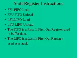
Shift Register • Shift register has a clock, a serial input (Sin), a serial output (Sout), and N parallel outputs (Q[N-1:0]) • A new bit is shifted in from Sin on each clock edge • All the subsequent contents are shifted forward • The last bit in the shift register is available at Sout • Used as serial-to-parallel converter • Converts serial input (Sin) to parallel output (Q[N-1:0]) • Don’t be confused with shifters, which are combinational logic blocks that shift an input by a specified amount
Shift Register with Parallel Load • Parallel-to-serial converter • When Load = 1, acts as a normal N-bit register • When Load = 0, acts as a shift register • Now a shift register can act as • Serial-to-parallel converter (Sin to Q[N-1:0]) • Parallel-to-serial converter (D[N-1:0] to Sout)
Verilog Representation `timescale 1ns / 1ns module shiftreg_tb(); regclk, reset, load, sin, reg [7:0] d; wire [7:0] q; wire sout; parameter clk_period = 10; shiftregshiftreg_uut (.clk (clk), .reset (reset), .load (load), .sin (sin), .d (d), .q (q), .sout (sout)); always begin clk = 1; forever #(clk_period/2) clk = ~clk; end initial begin load = 1'b0; d = 8'h00; #3; load = 1'b1; d = 8'h5A; #(clk_period); load = 1'b0; d = 8'h00; end initial begin sin = 1'b0; #3; sin = 1'b1; #(clk_period); sin = 1'b1; #(clk_period); sin = 1'b0; #(clk_period); sin = 1'b1; #(clk_period); sin = 1'b1; #(clk_period); end endmodule module shiftreg #(parameter N = 8) (input clk, input reset, load, input sin, input [N-1:0] d, output reg [N-1:0] q, output sout); always @(posedgeclk or posedge reset) begin if (reset) q <= 0; else if (load) q[N-1:0] <= d; else q[N-1:0] <= {q[N-2:0], sin}; end assign sout = q[N-1]; endmodule
Serial-to-Parallel Application • RS-232 or UART communication RxD TxD http://tutorial.cytron.com.my/wp-content/uploads/2012/02/uartreceiver1.gif
Floor and Ceiling Functions • Floor function maps a real number to the next smallest integer • Floor(x) is the largest integer, not greater than x • Ceiling function maps a real number to the next largest integer • Ceiling(x) is the smallest integer, not less than x Example
Barrel Shifter Design w/ nMOSFET A3 D3 S=1 A2 D2 S=2 A1 D1 S=3 A0 D0 S=0 (No Shift) S=1 S=2 S=3 Prof. Sean Lee’s Slide, Georgia Tech
Barrel Shifter Design w/ nMOSFET A3 A3 A3 A3 A3 D3 S=1 A2 A2 D2 S=2 A1 D1 S=3 A0 D0 S=0 (No Shift) S=1 S=2 S=3 Prof. Sean Lee’s Slide, Georgia Tech
Barrel Shifter Design w/ nMOSFET A3 D3 = A3 S=1 A2 D2 = A3 S=2 A1 D1 = A2 S=3 A0 D0 = A1 S=0 (No Shift) S=1 S=2 S=3 Prof. Sean Lee’s Slide, Georgia Tech