Truss Analysis
Truss Analysis. This tutorial will show you how to determine the forces in each member of a truss using Working Model. Change Units. Change the units to feet and pounds using the View pull-down menu. Circle .

Truss Analysis
E N D
Presentation Transcript
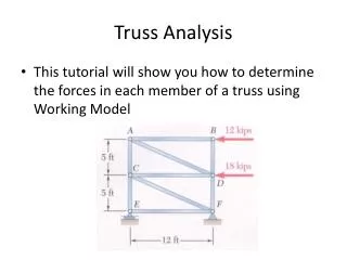
Truss Analysis • This tutorial will show you how to determine the forces in each member of a truss using Working Model
Change Units Change the units to feet and pounds using the View pull-down menu.
Circle Create a small circle using the Circle button. Change the radius of the selected circle using the Radius input box.
Move the circle to (0,0) using the x and y location input boxes.
Move the pasted circle to (0,5) using the x and y location input boxes.
Zoom to Extent Copy and paste circles and place them at (0,5), (0,10), (12,0), (12,5) and (12,10). Use the Zoom to Extent button to see all of the circles.
Rod Using the Rod button, create a rod that connects two of the circles using the centers of the circles.
Continue using the Rod button to create the rest of the truss members. Make sure to use the centers of the circles to ensure the correct geometry.
Text Using the Text button, label all of the corners of the truss.
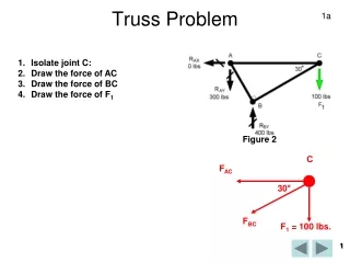
Create circles with connecting rods to form the reactions at E and F. Point F is a pinned connection that requires two components, and Point E requires only a normal force.
Force Force input boxes Using the Force button, apply forces at Points B and D. Use the Force input boxes to ensure the correct direction and magnitude in both the x and y directions.
Anchor Using the Anchor button, anchor the three circles at the reaction points.
Select one of the truss members. Using the Measure drop-down menu, place a Tension measurement output box next to the truss. Do this for all of the required members, including the rods representing the reactions.
Reset Run Execute the program by pressing the Run button. The tension (or compression) within the selected member will be shown in the output box. After running the program, press the Reset button to stop execution.