Download
1 / 33
350 likes | 588 Views
Design of stay vanes and spiral casing. Revelstoke, CANADA. Guri-2, VENEZUELA. Aguila, ARGENTINA. Sauchelle-Huebra, SPAIN. Sauchelle-Huebra, SPAIN. Three Gorges Turbine, GE Hydro. The spiral casing will distribute the water equally around the stay vanes

E N D
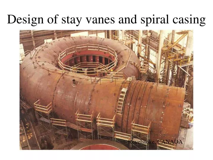
Design of stay vanes and spiral casing Revelstoke, CANADA
The spiral casing will distribute the water equally around the stay vanes In order to achieve a uniform flow in to the runner, the flow has to be uniform in to the stay vanes.
Streamline Flow in a curved channel
m Newton 2. Law gives: 1
The Bernoulli equation gives: Derivation of the Bernoulli equation gives: 2
Equation 1 and 2 combined gives: 1 2 Free Vortex
Inlet angle to the stay vanes cm ai cu
Find the tangential velocity: R0 R By
Example C L4 Flow Rate Q = 1,0 m3/s Velocity C = 10 m/s Height By = 0,2 m Radius R0 = 0,8 m Find: L1, L2, L3 and L4 L1 q L3 R0 R L2 By
Example C L4 Flow Rate Q = 1,0 m3/s Velocity C = 10 m/s Height By = 0,2 m Radius R0 = 0,8 m L1 q L3 R0 R L2 By
Example C L4 Flow Rate Q = 1,0 m3/s Velocity C = 10 m/s Height By = 0,2 m Radius R0 = 0,8 m We assume Cu to be constant along R0. At q=90o, Q is reduced by 25% L1 q L3 R0 R L2 By
Example C L4 Flow Rate Q = 0,75 m3/s Velocity Cu = 12,9 m/s Height By = 0,2 m Radius R0 = 0,8 m L1 q L3 R0 R L2 By
Example C L4 Flow Rate Q = 0,75 m3/s Velocity Cu = 12,9 m/s Height By = 0,2 m Radius R0 = 0,8 m L1 q L3 R0 R L2 L2 = 0,35 m L3 = 0,22 m L4 = 0,10 m By
B R0 Find the meridonial velocity from continuity: k1 is a factor that reduce the inlet area due to the stay vanes
Spiral casing design procedure • We know the flow rate, Q. • Choose a velocity at the upstream section of the spiral casing, C • Calculate the cross section at the inlet of the spiral casing: • Calculate the velocity Cu at the radius Ro by using the equation:
Spiral casing design procedure • Move 20o downstream the spiral casing and calculate the flow rate: • Calculate the new spiral casing radius, r by iteration with the equation:
Outlet angle from the stay vanes cm a cu
Design of the stay vanes • The stay vanes have the main purpose of keeping the spiral casing together • Dimensions have to be given due to the stresses in the stay vane • The vanes are designed so that the flow is not disturbed by them
Flow induced pressure oscillation Where f = frequency [Hz] B = relative frequency to the Von Karman oscillation c = velocity of the water [m/s] t = thickness of the stay vane [m]
Where A = relative amplitude to the Von Karman oscillation B = relative frequency to the Von Karman oscillation