Download
1 / 10
180 likes | 1.75k Views
Design and Analysis of a Spiral Bevel Gear. Matthew Brown April, 2009. Gear Theory and Design. Recommended design methodology published by American Gear Manufacturing Association (AGMA) Gear teeth primarily designed for two factors:

E N D
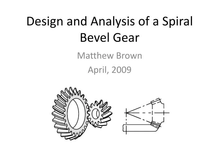
Design and Analysis of a Spiral Bevel Gear Matthew Brown April, 2009
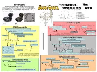
Gear Theory and Design • Recommended design methodology published by American Gear Manufacturing Association (AGMA) • Gear teeth primarily designed for two factors: • Resistance to pitting caused by Hertzian contact stresses • Accounts for contact pressure between two curved surfaces and therefore considers load sharing between adjacent gear teeth as well as load concentration that may result from uncertainties in manufacturing • Bending strength capacity based on cantilever beam theory • Accounts for compressive stresses at the tooth roots caused by the radial component of the tooth load; the non-uniform moment distribution of the load resulting from the inclined contact lines on the gear teeth; stress concentration at the tooth fillet; load sharing between adjacent contacting teeth; and lack of smoothness due to low contact ratio
Material Selection and Processing • In this application, spiral bevel gear materials are limited to only those which are easily carburized and case-hardened in order to provide high wear resistance and high load carrying capacity • SAE 9310 Steel selected • Material processing: • Heat treatment • Convert weaker grain structures to stronger ones • Tempering • Relieve brittleness and internal strains prior to machining • Carburization • Adds high hardness and strength at surface and toughens core to withstand impact stress
Bevel Gear Loading • Torque application to a bevel gear induces tangential, radial, and separating loads assumed to act as point loads applied at the mid-point of the gear tooth • Reaction loads are a result of the tapered roller bearings that support the gear shaft and counteract the gear loads • Loads are primarily a function of torque, pitch diameter, pitch angle, pressure angle, and face width • Loads and bending moments are calculated based on a vectoral combination of two planes
Fatigue Analysis • Performed at the two most critical sections of the gear shaft, sections A-A and B-B shown previously • Principle steady stress is calculated from vibratory bending, steady torsion, and normal stress, then converted into an equivalent vibratory stress based on fatigue data at 106 cycles • Endurance limit of gear is modified for size effect factor, correlation factor, surface finish factor, and reliability factor • Margin of Safety calculated using • Results: • M.S. @ A-A = 0.48 • M.S. @ B-B = 3.34
Static Analysis • Federal Aviation Administration requires static analysis be performed at 2X the endurance limit – analysis conducted at about 2.5X (590HP) • Similar process as fatigue analysis except the Margin of Safety is calculated by: • Results: • M.S. @ B-B = .87
Hertz Stresses • Must first calculate the geometry factor with an iterative procedure: • Then calculate Hertz stresses using: • Results: • Hertz stresses calculated = 180.6 ksi • AGMA allowable stress = 250 ksi
Bending Strength Capacity • Must first calculate the geometry factor with an iterative procedure: • Then calculate bending strength in gear teeth using: • Results: • Bending stresses calculated = 31.5 ksi • AGMA allowable stress = 40 ksi
Gear Life Calculations • Life calculated using Miner’s rule: • The portion of useful fatigue life used up by a number of repeated stress cycles at a particular stress is proportional to the total number of cycles in the overall fatigue life of the part. • Five maneuvers (1.53%) of anticipated helicopter flight spectrum produce damage • Damage accumulation calculations performed for both high cycle fatigue and GAG (low cycle fatigue) for both Bending Life and Durability Life – all calculations result in unlimited life
Conclusion • All analysis resulted in positive margins of safety and unlimited gear life in the intended application • All stress calculations are within the recommended allowable stress values published by the AGMA • Design is safe for operation