Download
1 / 19
190 likes | 392 Views
CLIC Survey and alignment. OUTLINE Strategy Review of specific tasks Development of sensors Fiducialisation & PACMAN. 02/09/2014. CLIC (intro). CLIC, module & pre-alignment. CLIC & modules:

E N D
CLIC Survey and alignment • OUTLINE • Strategy • Review of specific tasks • Development of sensors • Fiducialisation & PACMAN 02/09/2014 H. MAINAUD DURAND on behalf of the CLIC active pre-alignement team
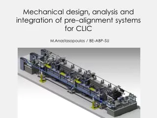
CLIC, module & pre-alignment • CLIC & modules: • CLIC (Compact Linear Collider): study for an electron-positron collider, with a center of mass energy of 3 TeV (Length > 40 km for 3TeV) • Based on a two beam acceleration concept • The two main linacs consist of more 20 000 modules (with a 2m length) • Pre-alignment case: • The components must be pre-aligned @ better than 14 um w.r.t a straight reference line over a sliding window of 200m • An active pre-alignment is needed: the position of the components is determined by sensors, and is re-adjusted by actuators in a continuous way.
Introduction • Survey and alignment: • In all the areas (damping ring, main linac, BDS, transfer lines,…) • For all the components, from 10 µm in the BDS to a few mm in the beam dumps • At all the stages of the project • Geodetic studies before excavation • Installation of geodetic networks as soon as the tunnel floor is ready • Active pre-alignment before the first pilot beam, and then every 2-3 days… • Divided into several steps:
Strategy … Priorities on active pre-alignment From the performance point of view Compatibility with other systems & integration Affordable One solution feasible To qualify the first solution To replace the first solution with less drawbacks, according to the criteria below Alternative solutions • Criteria: • Performance • Cost • Low sensitivity to environment (humidity, pressure, T°) • High resistance to radiation • High resistance to magnetic fields • Low sensitivity to EMC • Easy to integrate • Easy to install • Easy to maintain Develop a catalog of methods, means according to the steps, size of components, requirements,…
Strategy Test setups Methods used for LEP (& St Gottard tunnel) Transfer of knowledge in 2010 (LHC pit: PM32) Metrological network proposed for CDR: Stretched wires + cWPS [patented] + HLS to model the catenary + biaxial inclinometers Geodetic studies concerning the geoid Studies of alternatives: RasDif (3 point alignment system) Lambda project (n-point alignment system) Labs TT1 TZ32 For CDR: cWPS [patented] Alternatives: oWPS [Brandeis University, Open source Raschain [NIKHEF] Development of Rad-Hard inclinometers Study of two configurations of actuators 3 DOF “snake system” 5 DOF cam movers Two Beam Modules (TBM) prototypes in lab sensors = + actuators TBM prototypes in CLEX
Strategy Labs Development of portable means: AT 401, Romer Arm Micro Triangulation FSI ? Validation by CMM measurements TBM prototypes in lab Combination of CMM measurements and portable means TBM prototypes in CLEX Special study with MME, metrology, magnets, BI, magnetic measurements of a global solution of fiducialisation and alignment on common supports Monitoring of QD0 QD0 w.r.t 500 last meters of BDS Left side versus right side through survey galleries Development of a new solution Same solutions as for main linac &BDS Integration needed TZ32 Laser solution to be developed. FSI?
Task 1 : development of sensors Sensors (introduction) • Requirements: • Biaxial measurements (radial & vertical) • Range : > 3 mm • Resolution < 0.2 μm • Repeatability: < 1μm • Accuracy: < 5μm over the whole range • 3 solutions under development: • cWPS = capacitive Wire Positioning Sensors • oWPS = optical Wire Positioning Sensors • RasDif / RasNik Strategy in all cases: Validation on individual setups and calibration benches Inter-comparison on two beam modules prototypes in lab & accelerator environment
Task 1 : development of sensors Sensors : cWPS • 60 sensors installed in the LHC on the low beta triplets • Rad Hard (sensors up to 300 kGy, Remote electronics up to 50 kGy) • Resolution: 0.2 µm • But relative measurements only! • Latest achievements: • An isostatic mechanical interface allowing a repositioning within 1µm and an absolute calibration has been developed • A very accurate linearity bench: accuracy < 5 µm • An « absolute » bench • Dedicated lab with a temperature stable within ± 1ºC
Task 1 : development of sensors Sensors : oWPS • Main characteristics (from the manufacturer) • Resolution: < 0.1 μm • Range : +/- 5 mm (along two axes) • Repeatability: 2μm • Accuracy : < 5μm • Wire: Vectran • Latest achievements: • A very accurate linearity bench • A vectran wire (manufactured fiber spun from a liquid crystal polymer) visible to infra-red light and not antistatic silver plasma coated wire. • Resolution < 1 µm, interchangeability < 5 µm • Noise problem to be solved • Impact of temperature: ~ 6µm/°C to be corrected • Absolute calibration to be controlled.
Task 1 : development of sensors and actuators Sensors : Inclinometer • High precision biaxial inclinometer: • A Tilt Meter System (TMS) was developed by Fogale Nanotech, based on capacitive measurements for relative angle measurements in CTF2 • Rad hard, resolution < 1µrad • But so time-consuming to manufacture that the firm does not want to sell new ones any more • Latest achievements: • Althen / Sherborne high precision inclinometers ordered and installed on the TBM prototypes : • Equipped with a cWPS type interface • Repeatability : 2-3µrad • Interchangeability < 4-5 µrad • Status: • New absolute calibration bench to be developed • Absolute bench to be designed • Impact of temperature to be corrected • Rad hard version needed.
Task 1 : development of sensors and actuators Sensors : Next steps • Sensor compatible with accelerator environment: • Rad hard tests • EMC • Magnetic fields 2014-2015 • Sensor optimization: • Performance • Robustness • Mass production • Cost Not before 2015
First lessons learnt on TBTM concerning alignment • The alignment strategy on short range consists of a very accurate determination of the coordinate systems of: • The components • Their supports assembly • The sensors • combined with a micrometric adjustment • First lessons learnt: • CMM measurements are the most precise and accurate • CMM measurements of fiducials as a first step combined with AT401 + Romer arm measurements as a second step provide the best solution for micrometric alignments on site. • The first obtained results show that the followed strategy can be successful. The problem is that only the mechanical axis of the components was considered and not their electrical zero or magnetic axis. • one solution: perform at the same time the determination of the magnetic axis and electrical zero and the CMM measurements, object of the PACMAN project.
PACMAN project: • Propose and develop an alternative solution integrating all the alignment steps and technologies at the same time and location (CMM machine) • Technologies concerned: Ultra high precision engineering Magnetic measurements Beam Instrumentation Micrometric alignment Nano positioning Metrology
Scientific project • Short term: some key issues • Integration, ultra-high precision engineering and manufacturing • Magnetic measurements with a vibrating stretched wire (and alternative based on printed circuit boards rotating search coils) • Determination of the electromagnetic centre of BPM and RF structure using a stretched wire • Absolute methods of measurements: new measuring head for CMM, combination of FSI and micro-triangulation measurements as an alternative • Improve seismic sensors and study ground motion • Nano-positioning system to position the quadrupole and BPM Build a prototype alignment bench • Long term • Automation of the process • Simplification (method, duration, components) • Extrapolation to other components • Optimization of performances & precision in all domains • Preparation of industrialization
Marie Curie Initial Training Network (ITN): Innovative Doctoral Program CERN as host institution 15 associated partners Start date 1/09/2013 Duration: 4 years Web site:http://www.pacman.cern.ch/ EC fundings for 10 PhD students