Download
1 / 19
210 likes | 492 Views
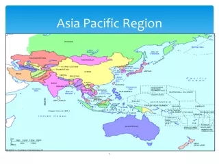
Implementation of Optical Submarine Systems as a backbone infrastructure in the Asia-Pacific region. Forum on: Implementation of decisions of the World Telecommunication Standardization Assembly-08 (WTSA-08) Nadi, Fiji - 16 September 2009. Paolo Rosa Head, Workshops and Promotion Division

E N D
Implementation of Optical Submarine Systems as a backbone infrastructure in the Asia-Pacific region Forum on: Implementation of decisions of the World Telecommunication Standardization Assembly-08 (WTSA-08) Nadi, Fiji - 16 September 2009 Paolo Rosa Head, Workshops and Promotion Division Telecommunication Standardization Bureau
Functional Grouping of ITU-T Rec.s on Optical Technology (3)
Construction, protection, installation and maintenance:L-series ITU-T Recommendations • Construction, installation and maintenance of all types of terrestrial and shallow water cables for public telecommunications, including optical cables, and the associated hardware. • Installation, jointing, protection and maintenance of cables. • Reliability and security, cable performance, field deployment and integrity of installations for mixed transmission media, such as hybrid fibre / copper cables.
The elements • Terrestrial Terminals Equipment, Repeaters & Optical Amplifiers • Branching Units (active / passive) • Cables, structures (AA,A,LW,L) • Deep sea and beach cable joints • The power feeding equipment
Type of Fibers: G.65x Series • non-dispersion shifted Single-Mode Fibre (SMF) defined in [G.652]; • Dispersion Shifted single-mode Fibre (DSF) defined in [G.653]; • Cut-off Shifted single-mode Fibre (CSF) defined in [G.654]; • Non-Zero Dispersion Shifted single-mode Fibre (NZDSF) defined in [G.655]; • Wideband Non-Zero Dispersion single-mode Fibre (WNZDF) defined in [G.656].
G.971-General features of optical fibre submarine cable systems
Cables Parameters and definitions • – Submarine portion: see [G.972] (1005). • – Optical submarine repeater: see [G.972] (1020). • – Cable Breaking Load: see [G.972] (5007). • – Double Armoured Cable: see [G.972] (5004). • – Fibre-Breaking Cable Load: see [G.972] (5008). • – Minimum Cable Bending Radius: see [G.972] (5032). • – Nominal Operating Tensile Strength: see [G.972] (5010). • – Nominal Permanent Tensile Strength: see [G.972] (5009). • – Nominal Transient Tensile Strength: see [G.972] (5011). • – Rock Armoured Cable: see [G.972] (5005). • – Single Armoured Cable: see [G.972] (5003). • – Relative Dispersion to Slope: see [G-Sup.40] (2006). • – Terminal Transmission Equipment: see [G.972] (1010).
Optical amplification: a) EDFA Multichannel applicationb) Raman amplification a) EDFA: atoms are pumped to a high energy state and then drop to a lower state, releasing their energy when a suitable wavelength photon passes nearby. b) Raman Scattering: nonlinear interaction between the signal and a pump laser within an optical fibre. As light travels down the fiber, energy is coupled from the shorter wavelength channels, boosting the amplitude of the longer wavelength (90 nm shift)
From design to operation • First idea & evaluation of alternatives (MIUs) • The first design & restoring techniques • The survey and implementation design • The power budget & Straight Line Diagram • Quality Assurance program, factory inspections and elements qualification • The manufacturing process and testing • The loading, system integration & monitoring • The laying & monitoring • The final splice & commissioning tests • The service
Restoring and Maintenance • Submarine system as a space satellite • Agreements for deposits of spare parts • Programming restoring and qualifications • Rerouting • Reparation
NEXT ACHIEVEMENTS • Multi-wavelength (up to 64 Coarse and Dense) bi-directional • 3rd windows (1 550 nm) • Bit rate up to 10 Gbit/s per fiber/direction/wavelength • Maximum span length with optical amplifiers up to 150 km, 700 km regeneration span • Maximum capacity 1.2 TBit/s => 5.12 TBit/s
Thank you ITU Committed to Connecting the World Paolo ROSA Head, Workshop and Promotion Division ITU - Telecommunication Standardization Bureau tsbpromo@itu.int