Download
1 / 14
140 likes | 362 Views
TDC for SeaQuest. Wu, Jinyuan Fermilab Jan. 2011. Introduction on FPGA TDC. There are two popular schemes for FPGA TDC: Multiple sampling based scheme: LSB: 0.6 to 1 ns. Delay line based scheme: LSB: 40 to 100 ps.

E N D
TDC for SeaQuest Wu, Jinyuan Fermilab Jan. 2011
Introduction on FPGA TDC • There are two popular schemes for FPGA TDC: • Multiple sampling based scheme: LSB: 0.6 to 1 ns. • Delay line based scheme: LSB: 40 to 100 ps. • We are currently working on a variation of the delay line based TDC called Wave Union TDC. Colleagues with requirements of TOF level resolution (< 50 ps) are welcome to contact us. TDC for SeaQuest
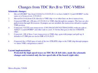
About the SeaQuest TDC • It is based on the multiple sampling scheme. • Most portions of the current TDC firmware are in good shape. • There are issues on TDC missing codes and wide RMS distributions. • The possible revisions are likely to be minor topology changes in various spots. TDC for SeaQuest
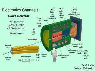
TDC Implemented with FPGA TDC for SeaQuest
Current Design (sch-chfend.tif) TDC for SeaQuest
Current Design (sch-quadedgedet.tif) TDC for SeaQuest
Clock Domain Changing Multi-Sampling TDC FPGA Multiple Sampling Q3 QF c0 c0 QE Q2 • Ultra low-cost: 48 channels in $18.27 EP2C5Q208C7. • Sampling rate: 360 MHz x4 phases = 1.44 GHz. • LSB = 0.69 ns. c90 QD Q1 c180 Q0 c90 c270 DV T0 T1 Trans. Detection & Encode 4Ch Coarse Time Counter TS Logic elements with non-critical timing are freely placed by the fitter of the compiler. This picture represent a placement in Cyclone FPGA TDC for SeaQuest
The Sampling Portion of the 1 ns TDC TDC for SeaQuest
The Top Layer of the 1 ns TDC TDC for SeaQuest
The Simulation of the 1 ns TDC TDC for SeaQuest
The End Thanks
TDC Using FPGA Logic Chain Delay • This scheme uses current FPGA technology • Low cost chip family can be used. (e.g. EP2C8T144C6 $31.68) • Fine TDC precision can be implemented in slow devices (e.g., 20 ps in a 400 MHz chip). IN CLK TDC for SeaQuest
FPGA TDC • A possible choice of the TDC can be a delay line based architecture called the Wave Union TDC implemented in FPGA. • Shown here is an ASIC-like implementation in a 144-pin device. • 18 Channels (16 regular channels + 2 timing reference channels). • This FPGA cost $28, $1.75/channel. (AD9222: $5.06/channel) • LSB ~ 60 ps. • RMS resolution < 25 ps. • Power consumption 1.3W, or 81 mW/channel. (AD9222: 90 mW/channel) TDC for SeaQuest Wave Union Launcher A In CLK
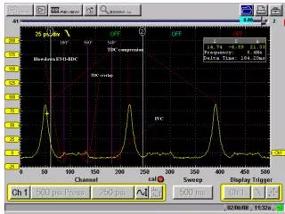
- - Measurement Result for Wave Union TDC A • Plain TDC: • delta t RMS width: 40 ps. • 25 ps single hit. • Wave Union TDC A: • delta t RMS width: 25 ps. • 17 ps single hit. Raw TDC + LUT Histogram 53 MHz Separate Crystal Wave Union Histogram TDC for SeaQuest