Download
1 / 40
420 likes | 596 Views
Isolated Single Phase Maximum Power Tracking Photovoltaic String Inverter. By Lloyd Caleb Breazeale Qualifying Examination Arizona State University March 10, 2010 . Discussion Topics . Isolated String Inverter Maximum Power Point Tracking Isolated Boost Control System

E N D
Isolated Single Phase Maximum Power Tracking Photovoltaic String Inverter By Lloyd Caleb Breazeale Qualifying Examination Arizona State University March 10, 2010
Discussion Topics • Isolated String Inverter • Maximum Power Point Tracking • Isolated Boost Control System • Inverter Control System • Anti-Islanding • Implementation and Test Results • Summary • Future Research
Isolated String Inverter • Challenges • Maintain input/output power balance • Maximum power point tracking (MPPT) • Low distortion output current • Input/output isolation • Rapid shutdown when utility source is absent (anti-islanding)
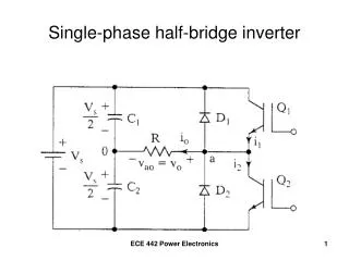
Topology Selection Full bridge isolated boost H-bridge inverter
Maximum Power Point Tracking Typical photovoltaic power curve No change Increment voltage Decrement voltage • Adjustments are made through • control of the array voltage
Incremental Conductance MPPT Equivalent conditions for maximum power • The power slope is determined from the incremental conductance • This method results in quick tracking without oscillations
Isolated Boost Voltage Control System • Maximum power tracking necessitates control of the input voltage Controller Plant approximation Time delay Low pass filter
Derivation of Small Signal Plant Model Basic relationships Combined Linearized
Input Voltage Control System Open loop frequency response Step response Root-locus for increasing PV impedance
Isolated Boost Simulation Results Inductor current (A) Input voltage (V) Reference step from 235 V to 600 V Load step from 500 W to 5000 W Reference step from 600 V to 235 V
Inverter Control System • Power balance necessitates control of the DC link voltage • Harmonic compensators are needed in the AC current loop • to attenuate harmonic distortion • The phase locked loop creates the ideal sine wave reference
Inverter Control System Models PLL filter Grid voltage filter DC link controller LCL filter DC link voltage filter LCL filter Grid current controller Grid current filter Harmonic compensators Link controller plant Time delay
Inverter Current Control Open loop response Grid voltage disturbance attenuation Sensor noise attenuation Reference tracking Discrete time controller Root locus
Phase Locked Loop Open loop system valid near zero phase error Discrete time open loop frequency response
DC Link Voltage Control Small signal plant model Open loop response Basic relationships Discrete time controller Combined Linearized at constant power
Inverter Discrete Time Simulation System interconnection Switchmode plant Phase locked loop Control system
Inverter Simulation Results Grid current step response Link voltage step response Time (s) Time (s)
Phase Locked Loop Simulation Time response of 60 degree phase step Normalized amplitude Time (s)
Anti-Islanding • Islanding is a condition in which a portion of the electric grid stays energized after the section has been disconnected from the main utility. • Worst case test condition is when the grid is neither supplying nor absorbing real or reactive power at instant of disconnect: • The greater RLC load quality factor, the more difficult islanding is to detect:
Anti-Islanding • Typical anti-island methods act to move the grid voltage beyond shutdown thresholds when the utility voltage source is absent • This is accomplished with a controlled instability of voltage, phase, or frequency • Common methods include Sandia Voltage Shift, Sandi Frequency Shift, and Slide Mode Shift
Sandia Voltage Shift • Current reference is a function of the difference between • instantaneous and nominal grid voltage: Voltage and current after disconnect Voltage trajectory after disconnect
Sandia Frequency Shift • Current wave shape is a function of the difference between • instantaneous and nominal grid frequency: where Positive chopping fraction Negative chopping fraction cf
Sandia Frequency Shift Simulation Inverter current wave shape Frequency trajectory after island Theoretical non-detection zone
Slide Mode Shift • Phase offset is a function of the instantaneous grid frequency: Slide mode shift phase characteristics
Slide Mode Shift Simulation Phase and frequency trajectory after disconnect Phase (rad) Shutdown thresholds Frequency (rad/s) Time (s)
Implementation Note: Maximum power tracking and anti-islanding were not included in this prototype. Also the input control was initially configured to regulate current not voltage as previously discussed
Hardware Power board Control board
The LCL Filter Attenuation of inverter voltage to grid current Damped LCL Average inverter voltage Grid voltage
Inverter Side Inductor High frequency flux density
Firmware RUN mode State flow
Switching Patterns Isolated boost Inverter
IsolatedBoost Converter Clamp capacitor voltage (50 V/div) Startup voltage at inductor output (250 V/div) Inductor output voltage (50 V/div) Startup inductor current (20 A/div) 2 ms/div 50 us/div
Inverter Output Without harmonic compensation With harmonic compensation Grid voltage (100 V/div) Grid current (5 A/div) 5 ms/div 100 Hz/div Generating VARs Absorbing VARs Grid voltage 25 V/div Grid current 1 A/div 5 ms/div
CompleteClosedLoop System Output power: 300 W Output power: 170 W Grid current (5 A/div) Grid voltage (100 V/div) Input voltage (100 V/div) DC link voltage (100 V/div) 10 ms/div 10 ms/div
Summary • A two stage power converter was analyzed, simulated, • and implemented • Other control aspects were explored: anti-island and MPPT • Complete functionality was verified at low power
Why so much effort into a system that is not new ? • To create a control system test platform • To discover areas of improvement • To develop working circuits that can be applied to new power converters • Personal benefit of increasing capability level
Future Research Control systems of power networks operating in a non traditional manner: • Energy storage • Intermittent distributed resources • Flexible power electronic circuits • Presence or absence of the greater electric grid • With communication interface