Download
1 / 46
511 likes | 811 Views
Requirements Engineering & User Requirements Notation. Daniel Amyot damyot@site.uottawa.ca http://www.UseCaseMaps.org/urn/ October 2002. Objectives. Part I: Requirements Engineering What is it? A RE approach Requirements characteristics Part II: User Requirements Notation (URN)

E N D
Requirements Engineering & User Requirements Notation Daniel Amyot damyot@site.uottawa.cahttp://www.UseCaseMaps.org/urn/ October 2002
Objectives • Part I: Requirements Engineering • What is it? • A RE approach • Requirements characteristics • Part II: User Requirements Notation (URN) • Motivations and objectives • Goal-oriented Requirement Language (GRL) • Use Case Maps (UCMs) • MSC generation • Relationships with other languages • Tools
Requirements Engineering Part I
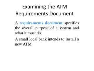
You said “Requirements”? • A requirement is an expression of the ideas to be embodied in the system or application under development • Requirements engineering is the activity of development, elicitation, specification, and analysis of the stakeholder requirements, which are to be met by systems • RE is concerned with identifying the purpose of a software system… and the contexts in which it will be used.
Requirements Development Requirements Management Analysis Specification Verification Elicitation Requirements Engineering Requirements Engineering Larry Boldt, Trends in Requirements EngineeringPeople-Process-Technology, Technology Builders, Inc., 2001
About the steps… • Requirements elicitation • Requirements discovered through consultation with stakeholders • Requirements analysis and negotiation • Requirements are analyzed and conflicts resolved through negotiation • Requirements specification • A precise requirements document is produced • Requirements validation • The requirements document is checked for consistencyand completeness
Business Goals/Objectives Vision and Scope Document User Requirements Quality Attributes Use Case Document System Requirements Functional Requirements Constraints Software Requirements Specification A Requirements Engineering Approach Adapted from Karl Wiegers, Software Requirements 1-7
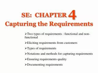
So many requirements…! • A goal is an objective or concern used to discover and evaluate functional and non-functional requirements. • A functional requirement is a requirement defining functions of the system under development • A non-functional requirement is a requirement characterizing a system property such as expected performance, robustness, usability, maintainability, etc. Non-functional requirements capture business goals/objectives and product quality attributes. • A user requirement is a desired goal or function that a user and other stakeholders expect the system to achieve
The Requirements Analyst • Plays an essential communication role • talks to users: application domain • talks to developers: technical domain • translates user requirements into functional requirements and quality goals • Needs many capabilities • interviewing and listening skills • facilitation and interpersonal skills • writing and modeling skills • organizational ability • RE is more than just modeling… This is a social activity! Karl Wiegers – In Search of Excellent Requirements
(Martin & Leffinwell) Why Manage Requirements ? Distribution of Defects Distribution of Effort to Fix Defects Code 1% Code 7% Other 4% Design 13% Requirements 56% Requirements 82% Other 10% Design 27%
TIME RE Process and Related Activities Identify Business Needs Why? What? How? Who? When? If-Then Does It? Where? Derive User & Functional Requirements Time Design Solutions Project Management Process Risk Management Process Quality Management Process Component & Configuration Management Process
Valid (or “correct”) Expresses actual requirements Complete Specifies all the things the system must do ...and all the things it must not do! Conceptual Completeness E.g. responses to all classes of input Structural Completeness E.g. no TBDs!!! Consistent Doesn’t contradict itself (satisfiable) Uses all terms consistently Note: inconsistency can be hard to detect, especially in concurrency/timing aspects and condition logic Formal modeling can help Towards Good Requirements Specs! Source: Adapted from Blum 1992, pp164-5 and the IEEE-STD-830-1993
Necessary Doesn’t contain anything that isn’t “required” Unambiguous Every statement can be read in exactly one way Clearly defines confusing terms E.g. in a glossary Verifiable A process exists to test satisfaction of each requirement “every requirement is specified behaviorally” Understandable (Clear) E.g. by non-computer specialists Modifiable Must be kept up to date! Towards Good Requirements Specs! Source: Adapted from Blum 1992, pp164-5 and the IEEE-STD-830-1993
Noise the presence of text that carries no relevant information to any feature of the problem. Silence a feature that is not covered by any text. Over-specification text that describes a feature of the solution, rather than the problem. Contradiction text that defines a single feature in a number of incompatible ways. Ambiguity text that can be interpreted in at least two different ways. Forward reference text that refers to a feature yet to be defined. Wishful thinking text that defines a feature that cannot possibly be validated. Jigsaw puzzles e.g. distributing requirements across a document and then cross-referencing Inconsistent terminology Inventing and then changing terminology Putting the onus on the development staff i.e. making the reader work hard to decipher the intent Writing for the hostile reader There are fewer of these than friendly readers Typical Mistakes Source: Steve Easterbrook, U. of Toronto
For Further Information… • B. A. Nuseibeh and S. M. Easterbrook, Requirements Engineering: A Roadmap. In A. C. W. Finkelstein (ed) The Future of Software Engineering, ACM Press, 2000 • http://www.cs.toronto.edu/~sme/papers/2000/ICSE2000.pdf • INCOSE Requirements Working Group • http://www.incose.org/rwg/ • Tools Survey: Requirements Management (RM) Tools • http://www.incose.org/tools/tooltax.html • See also http://www.systemsguild.com/GuildSite/Robs/retools.html • IEEE (1993) Recommended Practice for Software Requirements Specifications. IEEE Std 830-1993, NY, USA. • IEEE (1995) Guide for Developing System Requirements Specifications. IEEE Std P1233/D3, NY, USA. • RE Conference • http://conferences.computer.org/RE/ • Software Product Line Bibliography • http://www.iese.fraunhofer.de/Pulse/Bibliography/index.html
User Requirements Notation (URN) Part II
Stage 1 Stage 2 Stage 3 Requirements and Service Description Message Sequence Information Protocols, Procedures, Behaviour Motivation for URN (ITU-T SG17 Question 18) Informal requirements? Use Cases? MSC or UML interaction diagrams SDL or UML Statechart diagrams URN!
URN - Initial Objectives • Focus on early stages of design, with scenarios • Capture user requirements when little design detail is available • No messages, components, or component states required • Reusability of scenarios and allocation to components • Evaluation of architectural alternatives • Dynamic refinement capabilities • Behaviour and structure • Early performance analysis • Early detection of undesirable interactions
URN - Additional Objectives • Express, analyse and deal with goals and non-functional requirements (NFRs) • Express the relationship between business objectives/goals and system requirements • Capture reusable analysis (argumentation) and design knowledge (patterns) • Traceabilty and transformations to other languages • Particularly MSC, SDL, TTCN, and UML • Connect URN elements to external req. objects • Manage evolving requirements
Current Proposal for URN • Draft documents for Z.150, Z.151, Z.152 • http://www.UseCaseMaps.org/urn/ • Combined use of two complementary notations: • Goal-oriented Requirement Language (GRL) for NFRs (http://www.cs.toronto.edu/km/GRL/) • Use Case Maps (UCM) for Functional Requirements (http://www.UseCaseMaps.org/) • Create ITU-T standard by end of 2003 (Z.150-153)
GRL in a Nutshell • Goal-oriented Requirement Language — a graphical notation that allows reasoning about (non-functional) requirements • GRL is concerned with intentional elements, actors, and their relationships • Intentional elements model the “why” aspect — objectives, alternatives, as well as decision rationale and criteria — but not operational details • GRL may be mapped to scenario-based notations and thus supports reasoning about scenarios • GRL satisfies most of URN’s additional objectives
SystemSecurity Softgoal Break Hurt Some- Unknown Cost of Terminal Belief Contribution Make Help Some+ Equal Biometrics is no regular off-the-shelftechnology Security of Terminal Security of Host . . Make ? Argumentation Access Authorization Encryption Task Decomposition (AND) Correlation(side-effect) Authentication Identification Means-End Goal Cardkey Password Biometrics Basic GRL Notation
Satisficed SystemSecurity Weakly Satisficed Cost of Terminal Undecided Biometrics is no regular off-the-shelftechnology Weakly Denied Security of Host Security of Terminal . . Denied Access Authorization Encryption Authentication Identification Cardkey Password Biometrics Evaluations with GRL
Actor Resource Dependency Payment ElectronicAccountant TaxPayer ForwardTax Forms SystemSecurity Biometrics is no regular off-the-shelftechnology Securityof Host Security ofTerminal . . AccessAuthorization Cost of Terminal Encryption Authentication Identification Keep PasswordSecret Cardkey Password Biometrics ActorBoundary GRL Model with Actors
Key Points - GRL Introduction & Notation • GRL (Goal-oriented Requirement Language) provides an intentional view of a system, focusing on the “why” aspect • Goals provide the right abstraction level for many requirements activities • The basic elements of the GRL notation are goals, softgoals, tasks, qualified contribution and correlation links, means-end links, and decomposition links • GRL graphs document rationale of subjective issues • Evaluations of GRL graphs show the impact of qualitative decisions on high level softgoals
UCMs in a Nutshell • Use Case Maps – a graphical scenario notation for describing causal relationships between responsibilities • Scenario elements may (optionally) be linked to components, providing a grey-box view of systems • The intent of UCMs is to facilitate the integration, reusability, and analysis of scenarios, and to guide the design of high level architectures and detailed scenarios from requirements • UCMs satisfy most initial URN requirements
c) PassWord Plug-in b) Biometrics Plug-In Timer OR-Fork Pool StartPoint Stub AND-Fork Slot End Point Responsibility Component a) Root UCM
Electronic Accountant: Highlight Biometrics selected, Successful scenario
UCM Scenario Definitions • Enhances the behavioral modeling capability of UCM paths and path elements • Requires a path data model • Currently, global and modifiable Boolean variables • Scenario definition: initial values and start points • Used in conditions for OR-forks and dynamic stubs • Variables may be updated in responsibilities • Combined to a path traversal algorithm • Mapping rules for transformations
UserA AgentA AgentB UserB req chk msg1 vrfy User:A Agent:A Agent:B User:B upd chk upd vrfy ring ring req SN UserA Switch SN UserB msg2 chk req msg3 msg4 User:A Switch User:B vrfy chk msg5 ring req upd vrfy upd ring Refining UCMs with Messages
UMLsequence diagrams UMLcollaboration diagrams HMSC MSC’2000 Why Stop at MSCs? UCMspec(XML) Scenario Output(XML) MSC ’96 LOTOStest cases Documentation (ps, pdf, cgm) Performance models TTCN-3test cases
T2 UCMs and Performance • Device Characteristics • Processors, disks, DSP, external services… • Speed factors • Arrival • Characteristics • Exponential, or • Deterministic, or • Uniform, or • Erlang, or • Other • Population size Timestamp • Response Time • Requirement • From T1 to T2 • Name • Response time • Percentage TaxPayer Security E_Accountant T1 CheckBio Continue Ready Access Rejected • Components • Allocated responsibilities • Processor assignment • Responsibilities • Data access modes • Device demand parameters • Mean CPU load (time) • Mean operations on other devices • OR Forks • Relative weights (probability) Can generate Layered Queuing Networks (LQN) automatically!
GRL - UCM Relationship • Goal-based approach • Focuses on answering “why” questions • Addresses functional and non-functional requirements • Scenario-based approach • Focuses on answering “what” questions • Goals are operationalized into tasks and tasks are elaborated in (mapped to) UCM scenarios • Focuses on answering “how” questions
URN-NFR/GRL Goals, non-functional requirements, alterna-tives, rationales Informal Requirements, Textual Use Cases ? Structural Diagrams SDL, eODL, or UML class, object, component, & deployment diagrams URN-FR / UCMs Superimpose visually system level behavior onto structures of abstract components. Can replace UML use case & deployment diagams. ? MSC, UML Use Case Diagram & Activity Diagram Behavioral Diagrams MSC/SDL, or UML sequence, collabor., & statechart diagrams Testing and Performance LanguagesTTCN, LQN, ... URN — Missing Piece of the Modelling Puzzle? UCMs link to operationalizations(tasks) in GRL models UCMs represent visually use cases in terms of causal responsibilities UCMs visually associate behavior and structure at the system level UCMs provide a framework for making high level and detailed design decisions
GRL Tool: OME3 • Java tool, developed by Prof. Eric Yu, Dr. Lin Liu, and others (University of Toronto) • Conceptual modeling tool and model analysis tool • OME3 supports many frameworks • NFR (Non-Functional Requirements Framework) • i* (Strategic Actor-based Modelling Framework) • GRL (Goal-Oriented Requirements Language) • Based on TELOS • Exports to XML • Version 3.10: http://www.cs.toronto.edu/km/GRL/
UCM Tool: UCMNAV • By A. Miga, D. Petriu, D. Amyot and others, since 1997 • Editing and navigating of UCMs • Supports UCM path and component notations • Maintains bindings • Plug-ins to stubs, responsibilities to components, sub-components to components, etc. • Editing is transformation-based • Operations maintain syntactic correctness • Enforce some static semantics constraints • Scenario definitions • Path highlighting and MSC generation (Z.120, textual) • XML scenario generation • Performance analysis • Performance annotations • Generation of Layered Queuing Networks (LQN)
UCMNAV Facts • Load/save/import/export in XML • Developed in C++, GUI in Xforms • Requires an X-server • E.g. Xfree86 freeware (http://xfree86.cygwin.com/) • Multiple platforms are currently supported • Solaris, Linux, and Windows (all) • Current stable version: 2.0.1 • Freely available at http://www.UseCaseMaps.org • Free and Open Source: • http://ucmnav.sourceforge.net
UCMNav Documents • XML file format (conforms to UCM DTD) • Export of UCM figures • Encapsulated PostScript (EPS) • Maker Interchange Format (MIF) • Computer Graphics Metafile (CGM) • Scalable Vector Graphics (SVG) • Flexible report generation • Content options • PostScript, with PDF hyperlink information
URN – Emerging Projects • URN for Reverse-Engineering (KLOCwork Suite) • UCM/XML Scenarios to MSC, UML, TTCN, Doc… • URN and Requirements Management (DOORS) • URN and Requirements-based Design (synthesis) • URN and Performance Engineering (UCM2LQN) • ASM-Based Semantics for URN
Conclusion • URN • Combines goals and scenarios • Helps bridging the gap between requirements models and design models • GRL • For incomplete, fuzzy, non-functional requirements • Capture goals, objectives, alternatives and rationales • UCM • For operational and functional requirements • Enables analysis and transformations • Architectural alternatives and dynamic systems
Selected References • URN: http://www.UseCaseMaps.org/urn • ITU-T SG 17: Draft Recommendations Z.150, September 2002 • ITU-T SG 17: Draft Recommendations Z.151 and Z.152, February 2002 • D. Petriu and M. Woodside, Analysing Software Requirements Specifications for Performance. In: Third International Workshop on Software and Performance (WOSP 2002), Rome, Italy, July 2002 • D. Amyot and G. Mussbacher, URN: Towards a New Standard for the Visual Description of Requirements.In: 3rd SDL and MSC Workshop (SAM’02), Aberystwyth, U.K., June 2002. • G. Mussbacher, D. Amyot (2001), A Collection of Patterns for Use Case Maps. In: First Latin American Conference on Pattern Languages of Programming (SugarLoafPLoP 2001), Rio de Janeiro, Brazil, October 2001. • D. Amyot (2001), Specification and Validation of Telecommunications Systems with Use Case Maps and LOTOS. Ph.D. thesis, SITE, U. of Ottawa, Canada, September 2001. • A. Miga, D. Amyot, F. Bordeleau, D. Cameron, and M. Woodside (2001), Deriving Message Sequence Charts from Use Case Maps Scenario Specifications . In: Tenth SDL Forum (SDL'01), Copenhagen, Denmark, June 2001. • L. Liu and E. Yu (2001), From Requirements to Architectural Design –Using Goals and Scenarios. In: From Software Requirements to Architectures Workshop (STRAW 2001), Toronto, Canada, May 2001. • D. Amyot and G. Mussbacher (2000), On the Extension of UML with Use Case Maps Concepts. In: The 3rd International Conference on the Unified Modeling Language (<<UML2000>>), York, UK, October 2000. • R.J.A. Buhr (1999), Use Case Maps as Architectural Entities for Complex Systems. In: Trans. on Software Engineering, IEEE, Vol. 24, No. 12, December 1998, pp. 1131-1155.