Download
1 / 1
10 likes | 146 Views
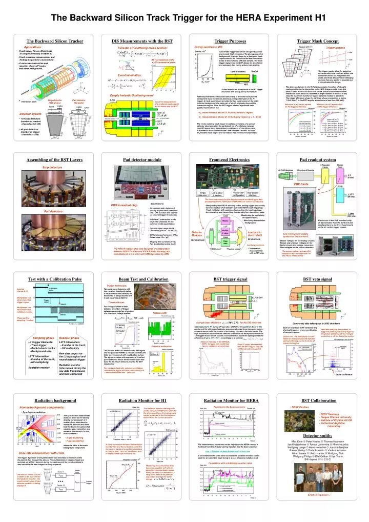
The Backward Silicon Track Trigger for the HERA Experiment H1. The Backward Silicon Tracker. DIS Measurements with the BST. Trigger Purposes. Trigger Mask Concept. Applications:. Energy spectrum in DIS. Inelastic eP-scattering cross-section:. Trigger patterns.

E N D
The Backward Silicon Track Trigger for the HERA Experiment H1 The Backward Silicon Tracker DIS Measurements with the BST Trigger Purposes Trigger Mask Concept Applications: Energy spectrum in DIS Inelastic eP-scattering cross-section: Trigger patterns • Track trigger for an efficient use • of a high luminosity of HERA-II; Calorimeter trigger rate at low energies becomes enormously high because of the photoproduction background. It is kept down by a (hadronic) track requirement in the central tracker that introduces a bias to the inclusive DIS data sample. The track trigger signal from the BST allows for an efficient and unbiased data taking without rate scaling. • Track curvature measurement and • finding the particle’s momentum; BST acceptance in the x, Q2 kinematical plane • Z-vertex reconstruction and • rejection of non-eP tracks • and other background. The trigger masks allow for selection of tracks which are confined within one azimuthal sector (22.5 degrees) and cross any three detector layers Merging of more than one sector is possible but it complicates the design. Event kinematics: The detector division in the R-Z plane provides formation of straight roads pointing to the interaction point. With 4 layers and 8 rings this gives 7 basic masks, but the event vertex spread around the nominal interaction point leads to a somewhat larger number of masks. In any case the maximum number of trigger patterns needed is about 60. The trigger efficiency drops for particles whose momentum is below 1 GeV (the Pt in the BST angular acceptance is less than 100 MeV). It also extends an acceptance of the H1 trigger for tracks with a very low Pt momentum. Deeply Inelastic Scattering event Fast response time and reduced sensitivity to a neutral background component make the silicon detectors an important part of the H1 trigger. A track requirement provides further suppression of the beam induced background, the main part of which originates beyond the interaction region. Thus the BST trigger offers a significant data quality improvement for: Strip detector (640 strips) Pad detector (32 pads) Inclusive measurements of a scattered electron with a calorimeter and the BST: Influence of a z-vertex spread on the trigger efficiency Influence of a XY-beam offset on the trigger efficiency • F2 measurements at low Q2 in the extended x region Detector system • FL measurements at low Q2 in the high y region (y = 1 – E’/E) • 144 strip detectors • (number of readout • channels = 92.160) • 48 pad detectors • (number of trigger • channels = 1536) The vertex pointing track trigger is realized by means of a special detector structure when the particles from eP collisions traverse the BST layers firing a predefined combination of the silicon pads. A number of those combinations – the so-called “masks” to cover all possible track angles and curvatures has been found empirically. Assembling of the BST Layers Pad detector module Front-end Electronics Pad readout system Strip detectors VME Cards The front-end boards for the detector control and the trigger data processing (the ALTERA chip EP20K300E is a core of each board): • Specifications: • 32 channels with digital and • analog outputs with controlled • ON / OFF function and internal • or external trigger thresholds; • Individual / subtraction mode • choice for channels for the • common mode suppression; • Dynamic input range 35 dB; • Controlled gain 15…30 mV / fC; • ENC (noise performance) 570 e; • Noise slope 15 e / pF; • Shaping time constant 30 ns; • Has a calibration pulse mode. PRO/A readout chip • Manipulating the PRO/A steering codes, setting trigger thresholds; • Synchronization of all detector pulses to HERA clock frequency; • Track validation with masks and computing the track topology; • Accumulating and transmitting the raw data from the silicon pads; Pad detectors • Monitoring the multiplicity • of triggered pads; • Monitoring the radiation • background; Electronics in the VME standard unify all data streams from the front-end and interface them to the level-1 and level-2 of the H1 central trigger system. Detector Modules Interface to the H1 DAQ Low noise power supply system for the front-end: 96 channels 384 channels • Bipolar voltages for the analog circuits; • Bipolar and unipolar voltages for the • digital circuits and voltage converters; • Bias voltages for the silicon detectors. Auxiliary functions: The PRO/A readout chip was designed in collaboration between DESY Zeuthen and IDE AS (Oslo, Norway) and manufactured in 1.2 um n-well CMOS process by AMS • Temperature • measurements • with a CAN chip. The system defines a power-ON sequence which is important for the PRO/A readout chip ! Beam Test and Calibration Test with a Calibration Pulse BST trigger signal BST veto signal Trigger hodoscope: Injected charge (8 fC) Two outermost detectors with low constant thresholds define a track and the third detector in the middle is being studied with 5 GeV electrons at DESY-II. Multiplexed raw data bit and the trigger signal Threshold scan For each pad of the middle detector a number of trigger pulses was counted as a function of a threshold voltage applied: Multiplexed raw data bit and the radiation monitor Plateau width Phase switch: sampling / readout A single layer efficiency for the DIS electrons Luminosity data taken prior to 2003 shutdown was measured in H1 during eP-operation of HERA. The particle’s track in the aperture of the silicon pad detector was reconstructed from two space points: an event vertex and a barycenter of the energy cluster in the calorimeter. The high momentum electrons were selected to exclude the background influence. The trigger masks which require a coincidence of any three layers provide the efficiency of up to accordingly to a formula: Such an event can fulfill randomly any physical trigger or even a combination of several triggers. Raw data analysis: the number of triggered pads is particularly high for the proton scattering off the rest gas molecules or off the beam line optics. Online veto: the multiplicity control helps for early background rejection without affecting events from the eP interaction region. Sampling phase Readout phase L1 Trigger Elements: - Track trigger; - Back-to-back tracks; - Background veto. L2TT information: - θ and φ of the track; - Hit multiplicity. • Electron energies in the SPACAL: • BST L1 trigger only (solid line) • Sector validation (dashed line) Event Z-vertex as measured with the BST trigger only. No additional cuts are applied Detector evaluation The plateau width is a measure of a MIP signal and the pedestal FWHM is a noise estimate (the latter was measured with a calibration pulse). The signal-to-noise ratio was control to select good detectors hence the threshold scan was done for all silicon sensors prior to the BST installation. Raw data output for the L2 topological and neural network trigger L2TT information: - θ and φ of the track; - Hit multiplicity. Radiation monitor (interrupted during the raw data transmission and then corrected) Radiation monitor For tracks defined with external scintillation counters the trigger efficiency of assembly of 3 detector modules was (96+/-2)% beam collimator Radiation Monitor for H1 Radiation Monitor for HERA Radiation background BST Collaboration Intense background components: Reaction to the beam currents • DESY Zeuthen The radiation monitor rate depends on the vacuum in HERA, therefore for the given conditions the background can be predicted in the first approxi- mation from the current product: • Synchrotron radiation: • DESY Hamburg • Prague Charles University • Institute of Physics AS CR • Rutherford Appleton • Laboratory The synchrotron radiation fan does not enter the H1 facility directly but some part of it scatters from absorbers to- wards the detector and does heat the beam line optics that causes a gas evaporation and worsens the vacuum. In turn this increases a Detector smiths • e-gas scattering • P-gas scattering Max Klein Peter Kostka Thomas NaumannJan Kretzschmar Tomas Lastovicka Mirek NozickaWolfgang Lange Hans Henschel Joachim MeiβnerRainer Wallny Doris Eckstein Vladimir ArkadovMilan Janata Ulrich Harder Wolfgang EickWolfgang Philipp Olaf Gräber Ilya TsurinBill Haynes H.-C.S-C. A linear correlation between the radiation monitor rate and the ionization current in the central trackers is used for chambers to control their “turn on” conditions and to explore their high voltage trips. The instantaneous count rate can be helpful for the HERA crew as a feedback from the detector during injection and the beam steering: http://h1lumiserver.desy.de:8080/main/h1mon.html In coincidence with some other counters the radiation monitor can be used for an automatic beam dump in a case of severe radiation load. where the latter is the main background component. Dose rate measurement with Pads The trigger algorithm of the pad detector was extended to monitor online the particle flux through the silicon. The multiplicities of triggered pads are summed up within 1 second, during the next second the result obtained is sent out while the next integral is being prepared. Correlation with scintillation counter rates Measuring the cumulative dose becomes possible with silicon detectors (besides beam losses when the energy is released in a very short time) as all particles deposit on average the same energy One silicon sensor (20 cm2) is taken as an area unit for the radiation monitor. The maximum rate over 48 pad detector modules is being displayed. Simply nice picture :-)