Download
1 / 81
810 likes | 984 Views
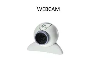
Planetary Imaging with Webcam and Computer. Clif Ashcraft, March 12, 2014. Webcams? For Astronomy?. Webcams are small digital video cameras that attach to your computer at the USB or Firewire port Many webcams are true CCD devices (like the Philips ToUcam)

E N D
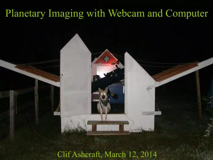
Planetary Imaging with Webcam and Computer Clif Ashcraft, March 12, 2014
Webcams? For Astronomy? • Webcams are small digital video cameras that attach to your computer at the USB or Firewire port • Many webcams are true CCD devices (like the Philips ToUcam) • They are lightweight & Cheap, $100 or so… • They produce monochrome or color digital videos in the .avi format, in a variety of resolutions • They are pretty much state of the art tech for high resolution planetary imaging
What’s Inside a typical webcam? Lens with NIR filter CCD chip behind window Microphone Video Circuit Board USB connector and cord
How do you use it for Astronomy?(you are probably going to void your warranty) 2) Add NIR blocking filter and 1.25” adapter 1) Remove lens and discard Replace the telescope eyepiece with the webcam Plug webcam into your laptop Point telescope at Mars… 3) 4) 5)
If you’re persistent and lucky, you will get some .avi video files which show planets jiggling around on the computer screen with fleeting glimpses of details on the edge of visibility, maybe better than what you might see squinting through an eyepiece, but still, nothing spectacular. You can also extract single frame snapshots from the video, but they tend to be blurry and don’t show the detail you could glimpse in the original “live” video. Wouldn’t it be great if we could somehow extract all the detail we know is in the video, and put it all into one picture?
Well, thanks to a Belgian amateur astronomer/computer programmer named Cor Berrevoets, we have a FREE downloadable program named REGISTAX which does just exactly that: http://registax.astronomy.net/html/v4_site.html • Here’s what Registax does: • Examines every frame of your video file • Does a critical evaluation of its quality. • Arranges frames in order of quality • Lets you pick a reference frame and how many of the best ones to keep. • Aligns each frame with the reference frame • Adds the frames digitally (stacking) • This gives an enormous improvement in signal to noise ratio (by √n). • Uses wavelet analysis to sharpen low contrast details in the image. Believe it or not. This image came from the video with the blurry single frame we saw in the previous slide! BUT, there are some details we need to deal with before we start getting pictures to rival the Hubble….
Critically Important Factor: Critical Details: • To get good results we need to match the resolution of the telescope to the digital sampling ability of the webcam • We do this by amplfying the focal ratio of the telescope until the smallest resolved image details are big enough to be realistically sampled by the pixels of the webcam CCD • We determine how much magnification we need using the digital sampling theorem - also the basis for high fidelity digital music recording and the operation of cell phones.
The Digital Sampling Theorem • In 1927 Harry Nyquist, an engineer at the Bell Telephone Laboratory determined the following principle of digital sampling: • When sampling a signal (e.g., converting from an analog signal to digital ),the sampling frequency must be at least twicethe highest frequency present in the input signal if you want to reconstruct the original perfectly from the sampled version. • His work was later expanded by Claude Shannon and led to modern information theory. • For this reason the theorem is now known as the Nyquist-Shannon Sampling Theorem
What does this all have to do with webcam astronomy? • The image made by the telescope optics is a two dimensional analog signal made up of spatial waveforms • A webcam is a digital sampling device Let’s re-state the sampling theorem in terms that relate to telescopic imaging using a webcam: • The sampling frequency implied by the pixel spacing on the webcam CCD must be at least twice the highest spatialfrequency present in the image to faithfully record the information in the image. If you violate this rule it’s called UNDERSAMPLING Undersampling is BAD…
Effects of Undersampling: Alias signals - illusions, not really there We can illustrate this with a digital scanner and a radiating line pattern: 60 dpi 13 dpi 302 dpi 23 dpi Oversampling is ok… Undersampling is not! How can we avoid undersampling in our imaging?
Moon image made with small refractor at f/6. Note sampling artifacts They are the result of using a focal ratio too small for proper sampling.
Let’s have a look at the To avoid undersampling we need to understand the sampling ability of our CCD
Monochrome vs Color Sensors If your camera has a monochrome sensor, you simply have a rectangular array of light sensitive regions called pixels grouped closely together so that there is very little space between them for light to be lost: The spacing between the pixels, s, is often just called the pixel size, usually expressed in microns, and is given in the technical specifications for the webcam. The sampling ability of the sensor is determined by the diagonal spacing of the pixels and is just spacing multiplied by the square root of two. Sampling frequency: vs = 1000/(s√2) samples/mm Nyquist frequency: vN = vs/2 line pairs/mm (lp/m) For a sensor with 5.6µ pixels this works out to: vN = 64 lp/mm To produce a color image from this kind of sensor requires the use of colored filters and taking three separate videos in rapid succession to give red, green and blue images.
A color webcam’s CCD, such as the one in the ToUcam is covered with an array of tiny filters called the Bayer matrix: Since there are samples taken in every frame for red, green and blue, only a single video is required to generate a full color image. There is a penalty however: lower resolution.
Note that in this scheme, the samples are twice as far apart as they were in the monochrome sensor. Color images are produced by separating into separate layers: Sampling frequency: vs = 1000/(2s√2) vs = 1000/(2s√2) vs = 1000/(2s) Nyquist frequency: vN = vs/2 For the ToUcam, s = 5.6 µ vN = vs/2 = 32 lp/mm vN = vs/2 = 32 lp/mm vN = vs/2 = 45 lp/mm These are the maximum spatial frequencies the webcam can accurately sample in any telescope image.
How do we avoid a grainy pixellated looking image with all these black holes? The most common way is simply to interpolate between the data we have. There is a fancy word for this: Debayerization. There are many algorithms for doing this. They differ only in how well they avoid making stupid mistakes. The simple, fast executing algorithms, like “Nearest Neighbor” make lots of mistakes, particularly on color boundaries, which result in color artifacts in the final image. Fancier ones, like HQLinear (available in Firecapture, and used on the Curiosity rover on Mars), don’t make the stupid mistakes but take longer to execute. They ALL are just interpolation and do not add any new information to the image. If you use debayerization of any kind, your resolution will be approximately half that of the equivalent pixel size monocrome camera. The other way is called dithering/drizzling and was invented by the Hubble Space Telescope imaging team to recover lost resolution in undersampled images. The HST was deliberately pointed fractional pixels away from the aiming point and multiple images were acquired, effectively getting data in the cracks and corners between the pixels. This is called dithering When scaled up by some factor, but not enlarging the pixels, these images could be digitally combined to give a higher resolution image, as though the pixels in the sampling device were smaller or the focal ratio were longer, by the scale factor. This is called drizzling The program AutoStakkert2 (AS!2) provides this functionality. It recovers color information from raw 8-bit color video to fill the gaps in the Bayer matrix by dithering: seeing and periodic errors in the telescope drive naturally point the telescope around the aiming point, allowing real data to be acquired which fills in the holes in the Bayer matrix. This allows color video to be obtained essentially at the same resolution obtained by the equivalent monochrome camera. Additionally, if 1.5x or 3x drizzling is selected, it can recover resolution lost by undersampling in color or monochrome video. But these color layers are full of holes!
Now let’s talk about the resolution of the telescope. First, some optical definitions:Focal length = FAperture = D = diameter of lens or mirrorFocal ratio = F/D(usually written f/# as in f/8 or f/2.5 or referred to as f-number or f-stop) image D F
Spatial Frequencies in the Telescope Image Diffraction causes the image of a point source to be spread out into a circular spot called the Airy disk: d d The diameter of the disk, d, is dependant only upon the focal ratio (f#) of the optical system and the wavelength, l, of the light used: d = 2.44lf# = 1.34f#(for green light l=0.55m)
Raleigh Limit for Resolution d/2 = 1.22lf# d/2 Two points of light separated by the radius of their Airy disks can just be perceived as two points. How can we convert this information into a spatial frequency?
Minimum Spatial Wavelength Based on Raleigh Limit d/2 Imagine the images of many points of light lined up in a row, each separated from the next by the radius of their Airy disks: The sinusoidal wave resulting from adding all the images can be used to define the minimum spatial wavelengths present in the image lmin = d/2 The highest resolved spatial frequency, nmax = 1/ lmin = 2/d = 1/1.22lf#.
So, in the image from the telescope, we find that the maximum spatial frequency, nmax, is given by a simple formula: Maximum spatial frequency = nmax = 1/1.22lf# For green light, l = 0.00055mm At f/6, nmax = 248 cycles/mm At f/15, nmax = 100 cycles/mm Now that we know how to calculate this, we can “match” the maximum spatial frequency with the Nyquist frequency, nN , of our webcam. Setting nmax = nNand plugging it into the above formula, we have, for 5.6 micron pixels: nN= 1/1.22lf# , which rearranges to: f# = 1/1.22lnN = minimum focal ratio to avoid undersampling f# = 1/(1.22* 0.00055*32) = 46 You would use half this, or f/23 if you used a monochrome camera, or were using AS!2 to dither/drizzle in the color information instead of debayering. In all cases, you must take four samples across the Airy disk
An alternate expression for the maximum spatial frequency is given by the cutoff frequency where the MTF goes to zero contrast: Maximum spatial frequency = nmax = 1/lf# For green light, l = 0.00055mm At f/6, nmax = 303 cycles/mm At f/15, nmax = 121 cycles/mm Setting nmax = nNand plugging it into the above formula, we have: nN= 1/lf# , which rearranges to: f# = 1/lnN = minimum focal ratio to avoid undersampling f# = 1/(0.00055*32) = 57 However, one could argue that critical sampling at the cutoff frequency is silly, since contrast goes to zero there. Somewhere between the focal ratio calculated from the Raleigh limit and the value based on the MTF intercept is probably best… Again, you would use half this, or f/29 if you used a monochrome camera, or were using AS!2 with raw color video to dither/drizzle in the color information instead of debayering.
Properly sampled Airy DiskNote four samples fit diagonally across the disk
Oversampling • Astronomers doing high resolution solar imaging routinely oversample by 50% • This seems to result in higher contrast, particularly at high spatial frequencies
The atmosphere also affects the image: The effect of atmospheric turbulence is to blur and bounce around the perfect Airy disk image until it doesn’t look so pretty any more: Assuming 5.6µ color camera with debayering Assuming 5.6µ color camera with dithering or 5.6µ mono. f/46 f/35 f/24 f/18 f/14 f/23 f/17.5 f/12 f/9 f/7 excellent good average poor bad V IV III II I 10 9 8 7 6 5 4 3 2 1 } Various qualitative seeing scales When the seeing is bad because the image is jiggling around, but slower than your frame rate, use the recommended focal ratio to achieve Nyquist sampling, Registax will eliminate the image motion and recover the detail. If the image motion is faster than the frame exposure can capture, or the image is defocused to a blur, you may reduce the focal ratio. The high spatial frequencies are no longer present in the image. Stopping down is often useful.
Much of the poor seeing in NJ this winter has been caused by the Jet Stream: http://www.weatherstreet.com/states/gfsx-300-forecast.htm Global warming has caused them to move south. They may be a permanent fixture.
Maximum Length of Video Planetary rotation imposes a limit on how many frames you can take with your webcam. Emmanuele Sordini has figured this out for us at: bloomingstars.com Here are his recommendations for Mars, Jupiter and Saturn based on keeping image blur smaller than the resolution of the telescope and sampling ability of a webcam:
How do we get the magnifications we need? • Barlow Lens or Powermate • Microscope Objective Transfer Lens • Eyepiece Projection
A Barlow Lens is a good way to achieve magnifications in the range of 2x to 3x and most amateurs already have one in their eyepiece box. It’s not a good idea to try to use a Barlow lens at a significantly higher power than its design magnification. Spherical aber-ation is introduced this way and can harm the image quality. Stacking of two Barlows to get 4x works better. Nagler sells Powermate image amplifiers that work well in this application although they are expensive. They are available in powers of 2x, 2.5x, 4x and 5x. They are used exactly like a Barlow lens.
Microscope objectives are a convenient way to gain high magnification with excellent optical quality. Typically, 5x, 10x, 20x and 40x are available. The 5x and 10x would be useful for this purpose. They are designed with a 160 mm back focal length, and the front working distance to the object being magnified is a little less than 160/M mm where M is the magnification. They are designed to work at the stated magnification (etched on the barrel of the lens) but can be used at slightly higher magnifications because we are not using their full numerical apertures with an f/6 beam.
The third easy way to couple a webcam to the telescope is using Eyepiece Projection. You need to make a short extension tube that fits and locks over the eye end of the eyepiece and which accepts the webcam adapter on the other end. A wide range of magnifications can be obtained by this method which has a long history of use for conventional astrophotography in the amateur community. Magnification achieved and the quality of the image obtained are dependant upon the power and quality of the eyepiece. Plössl eyepieces and orthoscopics should work well.
Many varieties of Webcams • Philips ToUcam has been a very popular and inexpensive webcam for astronomy and is the camera I started with. • An excellent entry level webcam costing under $100. • Difficult to find these days in the US. See AmazonUK and Ebay... • Celestron NexImage • Good low cost webcam, true CCD, 1280x720 pixels $99.95 • Higher performance (and more expensive) industrial and surveillance cameras used by advanced amateurs for astronomical purposes • The Imaging Source • DFK21: $350 for the color camera with 1-1/4 adapter. • DMK21: $390 for the B&W camera, $199 for filter wheel, $285 for filter set. • Point Grey Research CCD fire-wire cameras ~$700 or so • ZW Optical High performance CMOS cameras. • ASI120MC color camera, 1280x960 pixels, $298 • ASI120MM mono camera , 1280x960 pixels, $328 • ASI120MM plus filters and filter wheel, $498
Good places to start: Celestron NexImage The Imaging Source DBK21 ZW Optical ASI120MC/MM
Monochrome cameras have about twice the resolution of the color cameras and can use lower focal ratios to achieve Nyquist sampling. But, to get color images from a monochrome camera, you have to buy a color wheel and RGB filter set and then take three videos within the allotted time span to avoid rotational blur, compared to only one video with the color camera. It may be difficult to get an equally good quality videos in R, G and B if the seeing is not dependable where you image. The best imagers (guys like Damian Peach and Chris Go) use monochrome cameras, but they also tend to have good seeing where they do their imaging. If you have dependable good seeing, you may get better results with a monochrome camera and a color wheel, but you will work a lot harder and not get nearly as many images. If your seeing is less dependable, a one-shot color camera with a Bayer filter matrix built right on the CCD will work better for you. It is a lot cheaper to just get a color camera and forget about the color wheel. If you use AutoStakkert2 instead of debayering, you get the same resolution anyway, thanks to dither/drizzling… Bayer Matrix vs Color Wheel?
Camera Settings Guidlines • Uncheck all “Auto” boxes • Frame rate - 7.5 to 15 for older cameras like ToUcam, 30 to 60 fps with newer Firewire and USB2 cameras like TIS • Gain - set at 2/3 to 3/4 of full gain, increase to full if needed • Exposure - as short as possible to minimize blur due to image motion caused by seeing. Should be 1/25th sec or shorter. If not possible, increase gain and try again. • White balance - critical for realistic images. Two slider adjustments for blue and red balance. Adjust so the moon has no significant color. May be adjusted by pointing telescope at gray test card in daytime as well. • Experiment…
Computer stuff • The Computer • If you are setting up outside each time, the computer probably has to be a laptop. If you have a permanent observatory, a desktop is better. • You need a reasonably fast windows PC (no Macs, sorry, no software) • Buy as much RAM and hard drive space as you can possibly afford, a 500 gigabyte hard drive space is not too much! • Get an external 2 TB hard drive for your video library. • You need a free USB or Firewire port to plug the webcam into. • Webcam software: The driver on the CCD that came with it. • Download Firecapture: It’s free! and is the best astronomically oriented video capture program available. Powerful, user friendly, and saves data files with all your camera settings as well as timings and object info. http://firecapture.wonderplanets.de/download.html • Download Registax: It’s free! http://registax.astronomy.net/ • Registax tutorials: http://www.threebuttes.com/RegistaxTutorial.htm
} • Work Process: • Set up telescope with Barlow lens providing proper focal ratio • Center planet and focus with parfocal eyepiece • Attach camera and connect to computer • Capture raw 8-bit color video Native camera software or Firecapture • Debayer or Dither frames to recover color Firecapture, Registax or AS!2 • Evaluate quality of frames • Limit number of frames to use • Align frames • Stack frames • Sharpen frames with wavelets Registax • Derotate and stack individual images WinJUPOS • Registax, PIPP or AS!2
Noah My night assistant
My observatories in the snow… New Night Assistant, Boomer
10” f/17.6 Newtonian. Barlow lens mounted on-axis in front of small diagonal. Scope mounted on Losmandy G11 Germain Equatorial. Later installed in observatory. Used for Mars Opposition in 2003 and high resolution Jupiter pictures.
PC running Windows XP Pro Lots of RAM and HD Celestron CSC-1100 EdgeHD with ZWO ASI120MC camera
Now for Some of my Results The Moon
Magnified View of South Polar Region Mosaic, 45 individual segments of Gibbous Moon August, 2004, 12.5” f/6 Newtonian, 2x Barlow, ToUcam