Download
1 / 1
10 likes | 198 Views
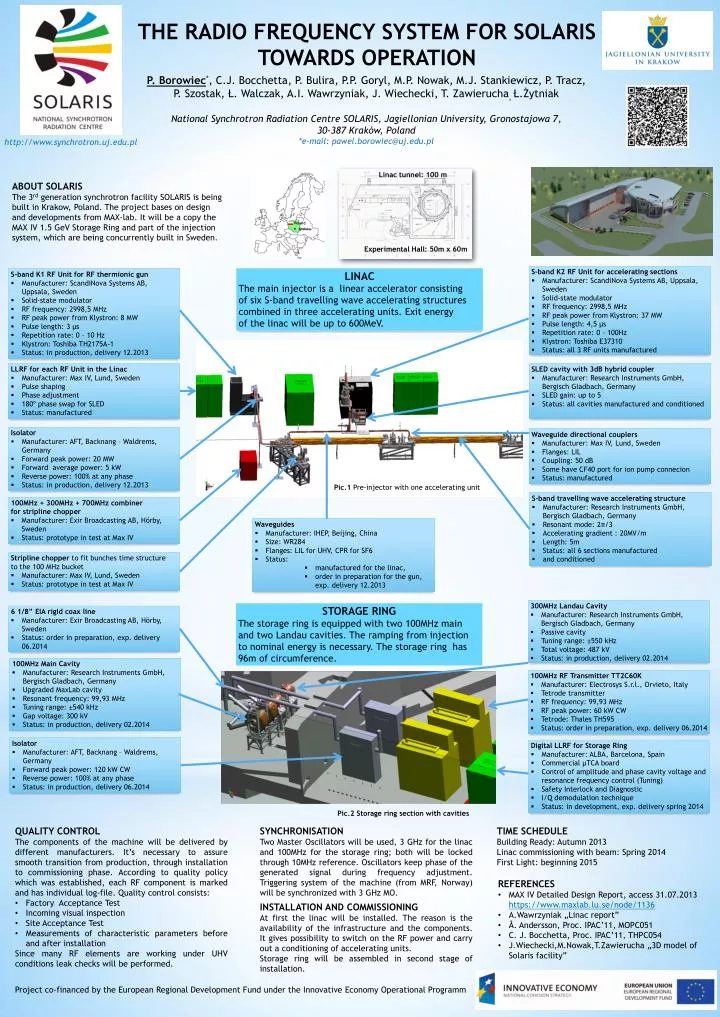
THE RADIO FREQUENCY SYSTEM FOR SOLARIS TOWARDS OPERATION. P. Borowiec * , C.J . Bocchetta , P . Bulira , P.P . Goryl , M.P . Nowak, M.J . Stankiewicz , P. Tracz , P . Szostak , Ł. Walczak , A.I. Wawrzyniak , J. Wiechecki , T . Zawierucha , Ł.Żytniak

E N D
THE RADIO FREQUENCY SYSTEM FOR SOLARISTOWARDS OPERATION P. Borowiec*, C.J. Bocchetta, P. Bulira, P.P. Goryl, M.P. Nowak, M.J. Stankiewicz, P. Tracz, P. Szostak, Ł. Walczak, A.I. Wawrzyniak, J. Wiechecki, T. Zawierucha,Ł.Żytniak National SynchrotronRadiation Centre SOLARIS, Jagiellonian University,Gronostajowa 7, 30-387 Kraków, Poland *e-mail: pawel.borowiec@uj.edu.pl http://www.synchrotron.uj.edu.pl Linac tunnel: 100 m ABOUT SOLARIS The 3rd generation synchrotron facility SOLARIS is being built in Krakow, Poland. The project bases on design and developments from MAX-lab. It will be a copy the MAX IV 1.5 GeV Storage Ring and part of the injection system, which are being concurrently built in Sweden. • S-band K2 RF Unit for accelerating sections • Manufacturer: ScandiNova Systems AB, Uppsala, Sweden • Solid-state modulator • RF frequency: 2998,5 MHz • RF peak power from Klystron: 37 MW • Pulse length: 4,5 µs • Repetition rate: 0 - 100Hz • Klystron: Toshiba E37310 • Status: all 3 RF units manufactured LINAC The main injector is a linear accelerator consisting of six S-band travelling wave accelerating structures combined in three accelerating units. Exit energy of the linac will be up to 600MeV. • S-band K1 RF Unit for RF thermionicgun • Manufacturer: ScandiNova Systems AB, Uppsala, Sweden • Solid-state modulator • RF frequency: 2998,5 MHz • RF peak power from Klystron: 8 MW • Pulse length: 3 µs • Repetition rate: 0 – 10 Hz • Klystron: Toshiba TH2175A-1 • Status: in production, delivery 12.2013 . Poland Kraków • LLRF for each RF Unit in the Linac • Manufacturer: Max IV, Lund, Sweden • Pulse shaping • Phase adjustment • 180º phase swap for SLED • Status: manufactured • SLED cavity with 3dB hybrid coupler • Manufacturer: Research Instruments GmbH, BergischGladbach, Germany • SLED gain: up to 5 • Status: all cavities manufactured and conditioned • Isolator • Manufacturer: AFT, Backnang – Waldrems, Germany • Forward peak power: 20 MW • Forward average power: 5 kW • Reverse power: 100% at any phase • Status: in production, delivery 12.2013 • Waveguide directional couplers • Manufacturer: Max IV, Lund, Sweden • Flanges: LIL • Coupling: 50 dB • Some have CF40 port for ion pump connecion • Status: manufactured Pic.1 Pre-injector with one accelerating unit • S-band travelling wave accelerating structure • Manufacturer: Research Instruments GmbH, BergischGladbach, Germany • Resonant mode: 2π/3 • Accelerating gradient : 20MV/m • Length: 5m • Status: all 6 sections manufactured • and conditioned • 100MHz + 300MHz + 700MHz combiner • for stripline chopper • Manufacturer: Exir Broadcasting AB, Hörby, Sweden • Status: prototype in test at Max IV • Waveguides • Manufacturer: IHEP, Beijing, China • Size: WR284 • Flanges: LIL for UHV, CPR for SF6 • Status: • manufactured for the linac, • order in preparation for the gun, exp. delivery 12.2013 Experimental Hall: 50m x 60m • Stripline chopper to fit bunches time structure • to the 100 MHz bucket • Manufacturer: Max IV, Lund, Sweden • Status: prototype in test at Max IV • 300MHz Landau Cavity • Manufacturer: Research Instruments GmbH, BergischGladbach, Germany • Passive cavity • Tuningrange: ±550 kHz • Total voltage: 487 kV • Status: in production, delivery 02.2014 STORAGE RING The storage ring is equipped with two 100MHz main and two Landau cavities. The ramping from injection to nominal energy is necessary. The storage ring has 96m of circumference. • 6 1/8” EIA rigid coax line • Manufacturer: Exir Broadcasting AB, Hörby, Sweden • Status: order in preparation, exp. delivery 06.2014 • 100MHz Main Cavity • Manufacturer: Research Instruments GmbH, BergischGladbach, Germany • Upgraded MaxLab cavity • Resonantfrequency: 99,93 MHz • Tuningrange: ±540 kHz • Gap voltage: 300 kV • Status: in production, delivery 02.2014 • 100MHz RF Transmitter TT2C60K • Manufacturer: ElectrosysS.r.l., Orvieto, Italy • Tetrode transmitter • RF frequency: 99,93 MHz • RF peak power: 60 kW CW • Tetrode: Thales TH595 • Status: order in preparation,exp. delivery 06.2014 • Isolator • Manufacturer: AFT, Backnang – Waldrems, Germany • Forward peak power: 120 kW CW • Reverse power: 100% at any phase • Status: in production, delivery 06.2014 • Digital LLRF for Storage Ring • Manufacturer: ALBA, Barcelona, Spain • Commercial µTCA board • Control of amplitude and phase cavity voltage and resonance frequency control (Tuning) • Safety Interlock and Diagnostic • I/Q demodulation technique • Status: in development, exp. delivery spring 2014 Pic.2 Storage ring section with cavities • QUALITY CONTROL • The components of the machine will be delivered by different manufacturers. It’s necessary to assure smooth transition from production, through installation to commissioning phase. According to quality policy which was established, each RF component is marked and has individual log-file. Quality control consists: • Factory Acceptance Test • Incoming visual inspection • Site Acceptance Test • Measurements of characteristic parameters before and after installation • Since many RF elements are working under UHV conditions leak checks will be performed. SYNCHRONISATION Two Master Oscillators will be used, 3 GHz for the linac and 100MHz for the storage ring; both will be locked through 10MHz reference. Oscillators keep phase of the generated signal during frequency adjustment. Triggering system of the machine (from MRF, Norway) will be synchronized with 3 GHz MO. TIME SCHEDULE Building Ready: Autumn 2013 Linac commissioning with beam: Spring 2014 First Light: beginning 2015 • REFERENCES • MAX IV Detailed Design Report, access 31.07.2013 https://www.maxlab.lu.se/node/1136 • A.Wawrzyniak „Linac report” • Å. Andersson, Proc. IPAC’11, MOPC051 • C. J. Bocchetta, Proc. IPAC’11, THPC054 • J.Wiechecki,M.Nowak,T.Zawierucha „3D model of Solaris facility” INSTALLATION AND COMMISSIONING At first the linac will be installed. The reason is the availability of the infrastructure and the components. It gives possibility to switch on the RF power and carry out a conditioning of accelerating units. Storage ring will be assembled in second stage of installation. Project co-financed by the European Regional Development Fund under the Innovative Economy Operational Programm