Enhanced Scan Based Flip-Flop for Delay Testing
Enhanced Scan Based Flip-Flop for Delay Testing. By Sudheer Vemula. Problem to be solved:-. To perform delay test, two vectors, V1 and V2, have to be applied in sequence V1 – For initializing the output of a particular path under test V2 – To observe the transition at the output

Enhanced Scan Based Flip-Flop for Delay Testing
E N D
Presentation Transcript
Enhanced Scan Based Flip-Flop for Delay Testing By Sudheer Vemula Vemula: ELEC7250
Problem to be solved:- • To perform delay test, two vectors, V1 and V2, have to be applied in sequence • V1 – For initializing the output of a particular path under test • V2 – To observe the transition at the output • The problem is, if we want to apply two independent vectors to the scan chain of flip-flops, we will loose the initialization of the circuit. • This problem can be solved by inserting hold latches, with an additional HOLD signal, to each scan flip-flop. • Area over head and delay in the signal path are increased. • Problem to be solved:- We need hold latches which have less area overhead and time delay. Vemula: ELEC7250
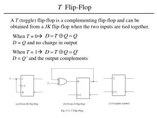
Background • Two widely used delay test techniques are • Launch from Capture • V2 is obtained from the response of V1 • Launch from Shift • V2 is one bit shift of V1 • The vector V2 can’t be arbitrary in both the techniques. Operation of Enhanced Scan Hold Flip-Flop: Vemula: ELEC7250
MUX based Latch Enhanced Scan Flip-Flop Hold Latches • Both designs of hold latches add delay, which will affect the performance. • The area overhead is also present. Vemula: ELEC7250
Supply Gating Scheme • This scheme is applied to the combinational logic present after the flip-flop (First Level Hold). • The state of the combinational logic is held in response to the first pattern by gating the VDD and GND of the first level logic gates. • Disadvantage:- • There might be leakage of charge due to the next level of logic gates Vemula: ELEC7250
Solution • The output should be pulled to either VDD or GND. • Add a latch. • Another Disadvantage:- • Power dissipation during the normal operation. • Solution – Block the operation of the latch during the normal operation of the circuit. For Normal Operation TC = 1 For Hold Mode TC = 0 Vemula: ELEC7250
Results Vemula: ELEC7250
Conclusions • The additional transistors in both PMOS and NMOS networks will increase the load at the output of the flip-flop, which will cause some additional delay compared to normal operation of the circuit without hold latch. • If fan outs are present at the output of the flip-flops, this will cause an increase the area and delay overhead. • For smaller circuits with more fan outs, MUX based latch may give better results for some cases. • There is an average reduction of 33% in area overhead with an average improvement of 71% in delay overhead and 90% in power overhead during normal mode of operation compared to enhanced scan implementation. Vemula: ELEC7250
Reference [1] S. Bhunia, H. Mahmoodi, A. Raychowdhury, and K. Roy, ‘‘A Novel Low-overhead Delay Testing Technique for Arbitrary Two-Pattern Test Application,’’ Proc. Design, Automation and Test in Europe, pp. 1136-1141, 2005 Vemula: ELEC7250