Download
1 / 19
260 likes | 1.17k Views
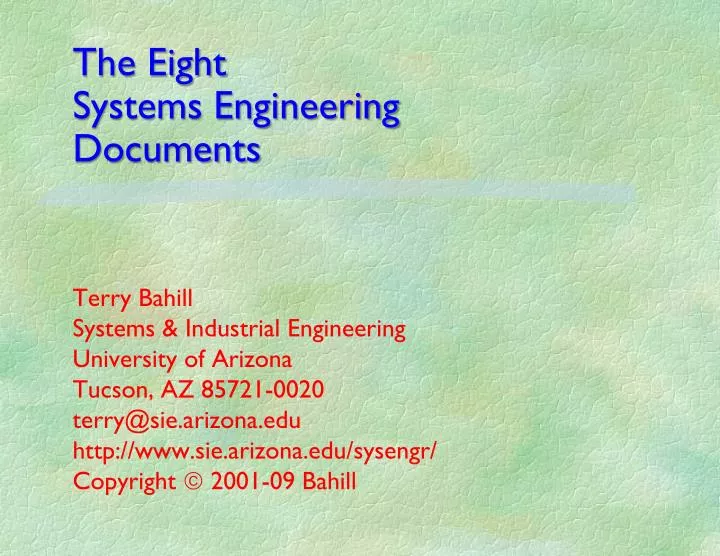
The Eight Systems Engineering Documents. Terry Bahill Systems & Industrial Engineering University of Arizona Tucson, AZ 85721-0020 terry@sie.arizona.edu http://www.sie.arizona.edu/sysengr/ Copyright 2001-09 Bahill. References.

E N D
The EightSystems Engineering Documents Terry Bahill Systems & Industrial Engineering University of Arizona Tucson, AZ 85721-0020 terry@sie.arizona.edu http://www.sie.arizona.edu/sysengr/ Copyright 2001-09 Bahill
References • W. L. Chapman, A. T. Bahill and W. A. Wymore,Engineering Modeling and Design,CRC Press Inc., Boca Raton FL, Chapters 5 and 6, 1992. • J. N. Martin, "Processes for engineering a system: an overview of the ANSI/EIA 632 standard and its heritage," Systems Engineering, 3(1), pp. 1-26, 2000. • W. A. Wymore, Model-Based Systems Engineering, CRC Press Inc., Boca Raton FL, Chapter 1, 1993. • http://www.sie.arizona.edu/sysengr/pinewood/pinewood.pdf © 2009 Bahill
The eight SE documents 1: Problem Situation 2: Customer Requirements 3: Derived Requirements 4: Verification and Validation 5: Concept Exploration 6: Use Case Model 7: Design Model 8: Mappings and Management © 2009 Bahill
The 8 systems engineeringdocuments are alive! © 2009 Bahill
1: Problem Situation1 • is the executive summary • states the problem* • specifies the system’s mission • explains customers’ needs and expectations • states the goals of the project • defines the business needs • prescribes the system’s capabilities • delineates the scope of the system • expresses the concept of operations • describes the stakeholders • presents the key decisions • shows the suggested architecture • highlights the preferred alternatives © 2009 Bahill
1: Problem Situation2 • This document summarizes the four most important program metrics: performance, cost, schedule and risk. • It describes the deliverables: what will be delivered to whom, when. • It is written in plain language and is intended for management and the public. © 2009 Bahill
2: Customer Requirements • contains a detailed problem statement and requirements extracted from the customer • based on the Specific Requirements sections of the use cases • contains a glossary of domain-specific terms and jargon • intended for management, the customer and systems engineering © 2009 Bahill
Input-function-output triples • Discover a function the system must perform • List an input that would be transformed into an output by that function • Noun – verb phrase – noun • For example, suppose your customer has a box of papers she wants to get rid of • (high level) • Input: box full of paper • Function: get rid of paper • Output: empty box and residue • (low level) • Input: paper • Function: burn paper • Output: ash © 2009 Bahill
3: Derived Requirements • technical description (or model) of the problem statement, customer requirements and additional derived requirements • intended for engineering • Alternative names: design requirements, system requirements, technical requirements © 2009 Bahill
4: Verification and Validation • Validating the system • building the right system • Verifying the system • building the system right • Validating requirements • ensuring that the set of requirements is correct, complete and consistent • Verifying requirements • Proving that each requirement has been satisfied by logical argument,inspection, modeling,simulation,analysis,test or demonstration. © 2009 Bahill
System Validation • shows that the system and the set of requirements satisfy the actual customer needs and expectations • checks the set of requirements for consistency and completeness • shows that a system model can satisfy the requirements • ensures that a real-world solution can be built and tested to prove that it satisfies the requirements • intended for systems engineering © 2009 Bahill
5: Concept Exploration • investigate alternative system designs • produce incipient architecture • use evaluation criteria in a tradeoff study • present sensitivity analyses • explain the do nothing alternative • should be readable by the public • Many tradeoff studies will be performed throughout the system life cycle. © 2009 Bahill
6: Use Case Model • contains many use case reports that describe the required behavior of the proposed system • will be the basis of the system design • intended for management, engineering, the customer, the public and systems engineering © 2009 Bahill
old 6: Functional Decomposition • A function (a verb phrase) is a process that transforms an input (a noun phrase) into an output (another noun phrase), e.g., burning changes paper into ash. • decompose the top-level system function into subfunctions • intended for systems engineering © 2009 Bahill
7: Design Model • class diagrams • sequence diagrams • state machine diagrams • activity diagrams • block definition diagrams • internal block diagrams • parametric diagrams • system models • e. g. Z = (SZ, IZ, OZ, NZ, RZ) • This model will be expanded into the implementation model and then the operational model © 2009 Bahill
8: Mappings and Management • mappings between the requirements of documents 2 and 3, the verification plan of document 3, the evaluation criteria of document 5, the functions of document 6 and the objects of document 7 • activity diagrams • user’s manual • risk analysis • Pert charts • schedules • work breakdown structure © 2009 Bahill
The Order in Which the 8 Documents Should be Started 1: Problem Situation 8: Mappings and Management (schedules) 6: Use Case Model 2: Customer Requirements 3: Derived Requirements 5: Concept Exploration 7: Design Model 4: Verification and Validation Then there are many iterations © 2009 Bahill
The SEMP These eight documents are the Systems Engineering Management Plan (SEMP), which is now being called the Integrated Master Plan (IMP) and the Integrated Master Schedule (IMS). © 2009 Bahill