Download
1 / 21
210 likes | 215 Views
Serial Powering of Silicon Strip Modules for the ATLAS Tracker Upgrade. Peter W Phillips STFC Rutherford Appleton Laboratory On behalf of RAL group and collaborators. Recall: Powering the present SCT. 4088 Detector Modules Independent Powering 4088 cable chains 22 PS racks

E N D
Serial Powering of Silicon Strip Modules for the ATLAS Tracker Upgrade Peter W Phillips STFC Rutherford Appleton Laboratory On behalf of RAL group and collaborators
Recall: Powering the present SCT • 4088 Detector Modules • Independent Powering • 4088 cable chains • 22 PS racks • 4 crates / rack • (up to) 48 LV and 48 HV channels / crate • Installation a major logistical challenge! • Overall efficiency ~40% • Cable R => voltage drops • Voltage limiter in line to protect against spikes due to sudden drops in load
Why Choose Serial Powering? The power consumed by n hybrids is always n I V, but the power wasted in cabling depends upon the powering scheme! Consider n hybrids with: hybrid current I hybrid voltageV off-detector cable resistance R DC-DC gaing and define x= IR/V for x = 6 (2.5A * 3.5 Ω / 1.5 V) X Target: 24 10 modules in series increases efficiency by factor 4 => Low V bad, large R and I are bad
Motivations Fewer Cables Fewer Connections Increased Efficiency Reduced Material Concerns Noise/electrical performance In fact SP systems are clean: local regulation helps chain current constant, therefore no IR drops Failure in the chain – loss of many modules … Why Choose Serial Powering?
Evolution of Serial Powering Circuitry AG Analog power AV Data Cmd Clk DG Digital pwr DV ? SSPPCB - 2006/7 38 mm x 9 mm SPPCB - 2006 111 mm x 83 mm • Hybrid • SSPPCB SPPCB - 2006 150mm x 150mm • ABCD3TV2
Six Module Stave • Based on CDF stave design • Uses several CDF “spare parts” • New bus cable (LBNL) • New thick film hybrid (LBNL) • With 4 ABCD chips • New serial powering PCB (RAL) • Two staves have been built • One at LBNL • One at RAL • The interface PCB carries a connector • All other connections are wire bonds • Picture shows stave assembled at RAL • “Module 2” left as hybrid for better comparison with single hybrid data Interface PCB & Cooling Hoses Module 0 Module 1 Hybrid 2 Module 3 Module 4 Module 5
Six Module Stave at RAL: RESULTS Input Noise (ENC) Input Noise (ENC) Gain (mV/fC) Gain (mV/fC) Results agree with expected ABCD performance!
Thirty Module “Stave Test Vehicle” A chain of 30 hybrids: Power input 123V, 0.8A Thick Film Hybrid for 6 ABCD chips with integrated Serial Powering circuitry: requires ~0.75A at 4V Carl Haber, LBNL
Interlude: Multi-Drop Signal Propagation • Whether we use Serial Powering or not, the desire to minimize the number of signal traces in a stave or supermodule design is clear. • The ABCD chip has five address lines: • No more than 32 chips may be connected to one command bus • The 30 module stave has six command buses • Each command bus serves five hybrids (30 chips in total) • For clock distribution, the thirty module stave design supports two options: • Connect 10 hybrids to each of 3 clock buses, or all 30 to one clock bus • Command waveforms typically look better than clock waveforms (fewer drops): • not always received and understood by ABCD • Phase adjustment can improve performance • Things don’t necessarily improve with larger signals (eg. M-LVDS) • Adding hybrids (or probes) lowers effective impedance (~40 ohm for 30 hybrids) • Beware of capacitive stubs when routing signals off external TTC tapes! • Studies continues using the “Test Vehicle” with different drivers and configurations • Test “bus cable” and “hybrids” being made to study effect of different stub lengths
Multi-drop Clock Distribution Even for “poor” clock waveforms, the AC coupled LVDS receiver triggers and ABCD returns the expected clk/2 signal.
Thirty Module Stave • Before the summer break, 7 modules and 2 hybrids had been mounted and tested on the stave. • Leakage current is stable and no additional breakdown on stave • Noise performance improves on stave, all are 900 electrons • Group of 5 modules share a common command line all read out together • Work to populate and test the stave continues in parallel with studies of communication issues using the “Stave Test Vehicle”
Occupancy Threshold (mV) Scan point Channel number VT50 (mV) Gain (mV/fC) Output Noise (ENC) Output Noise (mV) Channel number Input Noise (ENC) Thirty Module Stave: Preliminary Results S-curve
Sanity Check: ABCD Noise Slope SCT Barrel Module Bare Chip
Coming soon: ABCN • New front end chip for ATLAS upgrade Silicon Strip module development programme • 250nm CMOS IBM • 2.5V digital / 2.2V analogue • binary architecture • 128 channels of preamplifier/shaper/ comparator • 25nS peaking time • Additions to support novel powering schemes • On chip shunt regulators • On chip linear regulator for analogue supply • For details, see presentation given by Jan Kaplon in session A2
Coming Soon: SPi • Serial Powering Interface • Designed for generic SP use, but of great interest to ATLAS strip community • Programmable shunt regulator (>1A) • Two linear regulators • Integrated Monitoring • 7 AC-coupled LVDS comports • For details, see presentation by Marcel Trimpl in session B5 (next talk!)
Serial Power Options with ABCN • Wladek Dabrowski scheme • Use each ABCN’s integrated shunt regulator • Use each ABCN’s integrated power transistor(s) • Mitch Newcomer scheme • Use one external shunt regulator • Use each ABCN’s integrated power transistor(s) • SPi - like scheme • Use one external shunt regulator • Use one external power transistor • Most similar to what has been used with ABCD…
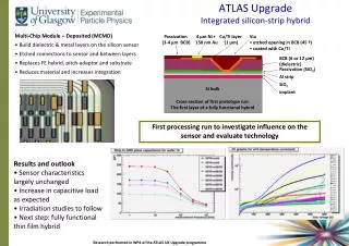
Baseline “Short Strip” Module Concept • 10cm*10cm detector • 4 sets of short strips • S/N after irradiation • Occupancy • 2 hybrids • 20 FE ASICs each • Bus cable under detector • Power, DCS, HV along one edge • Fast signals routed to the other edge
Coming soon: 20 chip ABCN Hybrid Data Link 1 Common TTC (serving 20x ABCN) DCS, Power, HV Data Link 0 Digital I/O Ashley Greenall, University of Liverpool • Primary aim: test 20 ABCN together on one hybrid • Secondary aim: evaluation of various power options • Power fed from one end, control and command from the other • Can be used with any powering scheme, where necessary by addition of external PCBs • IP • SP using discretes • SP with SPi • DC-DC • …
Baseline Stave Concept ~1.2m 12 + 12 single sided modules back-to-back An alternative supermodule design is also being studied • Based around double sided short strip modules • A suitable hybrid for this, using ABCN, is being produced by KEK • Wrap around design, so 40 chips / hybrid!
Related Activities • SP features in Pixel FE chip • see presentation given by Michael Karagounis in session A2 • Development of SP protection schemes • D Lynn, J Kierstad, BNL • Andreas Eyring, Bonn • Constant Current Source development • Jan Stastny, Prague AS
Summary • Serial Powering has been shown to work well • 6 and 30 module staves • noise in agreement with FE chip noise slope • Next generation ASICs for ATLAS strip modules with integrated SP features will arrive soon • Should have even better performance! • Remaining system issues being addressed • Custom current source • Protection schemes • Exciting Times for Serial Powering!