Download
1 / 34
550 likes | 1.73k Views
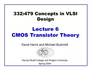
332:578 Deep Submicron VLSI Design Lecture 23 Latchup and Reliability. David Harris and Mike Bushnell Harvey Mudd College and Rutgers University Spring 2005. Material from: CMOS VLSI Design By Neil E. Weste and Harris. Outline. Reliability – CMOS reliability failures due to:

E N D
332:578 Deep Submicron VLSI DesignLecture 23 Latchup and Reliability David Harris and Mike Bushnell Harvey Mudd College and Rutgers University Spring 2005
Material from: CMOS VLSI Design By Neil E. Weste and Harris Deep Submicron VLSI Des. Lec. 23
Outline • Reliability – CMOS reliability failures due to: • Electromigration • Self-heating • Hot Carriers • Latchup • Latchup Prevention • Overvoltage • Time-Dependent Dialectric Breakdown (TDDB) • DRAM Soft Errors • Summary Deep Submicron VLSI Des. Lec. 23
Reliability • MTBF – Mean Time Between Failures • MTTF – Mean Time to Failure • FIT – Failures in Time = 109 X (failure rate/hour) • Good value is 1000 FIT or 1 failure in 114 years for 1 chip • Example: • System has 10-0 chips rated at 1000 FIT • Customer purchases 10 systems • Failure rate = 100 X 1000 X 10 = 106 FIT • One failure every 1000 hours (42 days) • Must keep FIT less than 100 FIT Deep Submicron VLSI Des. Lec. 23
Electromigration • Due to electron wind in wires • Big problem in Al wires – less troublesome in Cu, Al-Cu, or Al-Si wires • Due to different grain transport properties • Depends on current density J = I / wt • More likely in DC wires than in AC wires • Jdc is electromigration limit – should be < 1 to 2 mA/mm2 at T = 110 °C • Ea is defect activation energy Deep Submicron VLSI Des. Lec. 23
Self-Heating • High currents dissipate power in wire, raise its T • Hot wires have greater R and delay • Self-heating also speeds up electromigration • High but brief peak currents can even melt wires • Self-heating depends on RMS current density • Keep Jrms < 15 mA/mm2 for Al • Particularly bad for SOI -- poor thermal conductivity of SiO2 Deep Submicron VLSI Des. Lec. 23
Electromigration/Self-Heating • Mainly a problem in power and ground • Causes problems in gates, too • Fix by widening lines or reducing transistor sizes Deep Submicron VLSI Des. Lec. 23
Hot Carriers • During switching, e-- injected into gate oxide and get trapped • Changes I-V device characeristics • Reduces I in nFETs, increases I in pFETs • Maximum damage when Isub is large, nMOSFETS are in saturation, and input rises • Worst for inverters and NOR gates & for high supply voltages Deep Submicron VLSI Des. Lec. 23
Wearout from Hot Carriers • Makes nFETs too slow • Causes sense amps. and matched circuits to fail • Matched components degrade differently • Limit wear by limiting max. input rise time and stage electrical effort • Negative Bias Temperature Instability (NBTI) • Decreases pFET current as pFETs wear • Due to trapped holes in oxide coupled with interface state creation • Causes circuit failure due to delay and mismatch • NBTI depends on device electric field Deep Submicron VLSI Des. Lec. 23
Latchup • Causes shorting of VDD & VSS lines • Result: • Destroys chip or • Causes system failure – must power down to fix • Control with process innovations & circuit design • Thyristor circuit – embedded in every CMOS logic gate Deep Submicron VLSI Des. Lec. 23
Parasitic Transistor Location Deep Submicron VLSI Des. Lec. 23
Equivalent Analog Circuit Deep Submicron VLSI Des. Lec. 23
Latchup Failure Mechanism • Draw current through substrate – Vsub rises • Emitter-Base voltage drop becomes 0.7 V. • npn transistor turns on – current flows in well resistor • Base-Emitter voltage of pnp transistor rises • pnp transistor turns on when Vbe = -0.7 V • npn Base voltage raises due to positive feedback • At npn base-emitter voltage trigger point – emitter voltage snaps back and thyristor turns on • Stays on as long as V across 2 transistors > holding voltage • Terminals go to 4 V. and metal lines supplying latched-up circuit burn out Deep Submicron VLSI Des. Lec. 23
Latchup Triggering • Must trigger parasitic npn – pnp circuit • Must maintain holding state • Trigger with transient currents or voltages: • During power-up • External signals beyond operating ranges • Trigger with radiation pulses Deep Submicron VLSI Des. Lec. 23
Lateral Triggering • Current flows in emitter of lateral npn bipolar device • Intrigger = Vpnp-on anpn Rwell • Vpnp-on 0.7 V • anpn – common base gain of lateral npn • Rwell – well resistance Deep Submicron VLSI Des. Lec. 23
Vertical Triggering • When enough current is injected into emitter of vertical pnp • Like lateral case: • Current gets multiplied by common base gain • Causes voltage drop across emitter-base junction due to Rsubstrate • Holding (or sustaining) point • Stable operating point if current can be maintained • Needed current injection – unlikely to be caused by supply voltage transients, except in CMOS pad circuits Deep Submicron VLSI Des. Lec. 23
Latchup Scenarios • Whether latchup occurs – depends on: • Pulse widths • Speed of parasitic transistors Deep Submicron VLSI Des. Lec. 23
Latchup Scenario 1 Undershoot – output dips below VSSby > 0.7 V – latches up Deep Submicron VLSI Des. Lec. 23
Latchup Scenario 2 • pMOS overshoots VDD by > 0.7 V Deep Submicron VLSI Des. Lec. 23
Latchup Prevention • Latchup happens with: • bnpnbpnp > 1 + (bnpn + 1) (IRsubs + IRwellbpnp) IDD – IRsubs • IRsubs = Vbe npn Rsubs • IRwell = Vbe pnp Rwell • IDD = Supply current (total) Deep Submicron VLSI Des. Lec. 23
Solutions to Latchup • Solutions: • Reduce R values • Reduce bipolar transistor gains • Prevention: • Latchup-resistant CMOS processes • Layout techniques Deep Submicron VLSI Des. Lec. 23
Process • Si starting material, thin epitaxial Si on top of heavily doped substrate • Decreases substrate R • Sinks collector I of vertical pnp • The thinner the epi the better • Retrgrade well structure • Well bottom highly doped, top is more lightly doped, • Gives good transistors but reduces R deep in the well • Can increase holding V. above VDD • Hard to reduce b’s:bpnp = 10 to 100, bnpn = 2 to 5 Deep Submicron VLSI Des. Lec. 23
Internal Latchup Prevention • Use merged substrate/source contacts • Reduces Rsubs and Rwell • In most processes, latchup cannot happen if you use liberal substrate contacts • Every well needs a substrate contact • Connect each substrate contact through metal directly to a supply pad • Put substrate contracts as close to source transistor connection on the supply rail as possible • Conservative – use 1 substrate contact for every supply connection Deep Submicron VLSI Des. Lec. 23
Internal Latchup Prevention (cont’d.) • Put a substrate contact for every 5-10 transistors or every 25 to 100 mm • Pack n devices toward VSS, and p devices toward VDD • Avoid checkerboard transistor arrangements Deep Submicron VLSI Des. Lec. 23
I/O Latchup Prevention • Very susceptible to latchup – external voltages ring below GND or above VDD • Use guard rings • These spoil the parasitic bipolar devices by collecting minority carriers • Area penalty high, but must be used in outer space electronics to avoid radiation-induced latchup • Not so bad if you do this only for I/O drivers Deep Submicron VLSI Des. Lec. 23
I/O Guard Rings Deep Submicron VLSI Des. Lec. 23
I/O Guard Rings Deep Submicron VLSI Des. Lec. 23
Guard Ring Structure Deep Submicron VLSI Des. Lec. 23
n-Well Process Latchup Prevention • Use proven I/O structures • Physically separate n & p transistors with the bonding pad • Put n+ (p+) guard rings shorted to VSS(VDD) around p (n) transistors • Place source diffusion regions along equipotential lines for current flowing from VSS to p Well • Make source fingers perpendicular to current flow • Short n transistor source to substrate & p transistor source to n-well with metal along entire length Deep Submicron VLSI Des. Lec. 23
n-Well Process Latchup Prevention • Hard-wire n-well to power (via n+) to divert injected charge to VDD • Keep spacing between n-substrate & p transistor source contact minimal (collects minority carriers) • Keep spacing between substrate p+ and n transistor source contact minimal • All diffusion areas connected to external world must be surrounded by guard rings • SOI processes completely avoid latchup – no parasitic bipolar transistors • If VDD < 0.7 V, parasitic bipolar transistors never turn on Deep Submicron VLSI Des. Lec. 23
Overvoltage Failure • Due to: • Electrostatic discharge (ESD) • Oxide breakdown • Punchthrough • Time-dependent dielectric breakdown of gate oxide • Cause: • Breakdown & arcing across thin oxide • Exists maximum safe voltage for transistors • Often less than I/O standard voltage • Requires 2nd transistor type with thicker oxides and longer channel to handle higher I/O voltage Deep Submicron VLSI Des. Lec. 23
Time-Dependent Dielectric Breakdown (TDDB) • Gate oxides wear out due to damage from tunneling currents • Exponential dependent on T and tox • For 10-year life at T = 125 °C • Field across gate Eox < 7 MV/cm = 0.7 V/nm • Greatest problem during voltage overshoots • Noisy power supplies • Reflections on I/O pads Deep Submicron VLSI Des. Lec. 23
Soft Errors • In 1970’s, DRAMs sometimes flipped bits for no reason • Linked to alpha particles and cosmic rays • Collisions with particles create substrate e-- hole pairs • Carriers collected on dynamic nodes, disturbing the voltage • Minimize soft errors by having plenty of charge on dynamic nodes • Tolerate errors through ECC, redundancy • Particularly a problem with flip-chip technology due to radioactive decay from lead in solder bumps • Use aged lead and highly-purified Al wires Deep Submicron VLSI Des. Lec. 23
Summary • Reliability • Electromigration • Self-heating • Hot Carriers • Latchup • Latchup Prevention • Overvoltage • Time-Dependent Dialectric Breakdown (TDDB) • DRAM Soft Errors Deep Submicron VLSI Des. Lec. 23