Download
1 / 38
380 likes | 384 Views
This review covers the block diagram, state graph, array multiplier, and multiplication of signed binary numbers. It also explores the 2's complement multiplier, behavioral model for a faster multiplier, and SM charts for digital design.

E N D
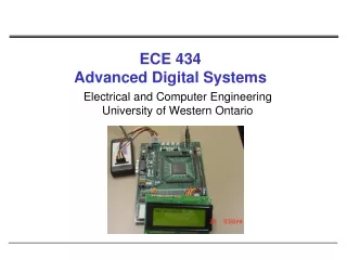
ECE 434Advanced Digital SystemL13 Electrical and Computer EngineeringUniversity of Western Ontario
Review: Block Diagram of a Binary Multiplier Ad – add signal // adder outputs are stored into the ACC Sh – shift signal // shift all 9 bits to right Ld – load signal // load multiplier into the 4 lower bits of the ACC and clear the upper 5 bits
Review: Multiplier Control with Counter (cont’d) • Increment counter each time a shift signal is generated • Generate K after n-1 shifts occured
Review: Array Multiplier • What do we need to realize Array Multiplier? AND gates = ? FA = ? HA = ?
Review: Multiplication of Signed Binary Numbers • How to multiply signed binary numbers? • Procedure • Complement the multiplier if negative • Complement the multiplicand if negative • Multiply two positive binary numbers • Complement the product if it should be negative • Simple but requires more hardware and timethan other available methods
Review: Multiplication of Signed Binary Numbers • Four cases • Multiplicand is positive, multiplier is positive • Multiplicand is negative, multiplier is positive • Multiplicand is positive, multiplier is negative • Multiplier is negative, multiplicand is negative • Examples • 0111 x 0101 = ? • 1101 x 0101 = ? • 0101 x 1101 = ? • 1011 x 1101 = ? Preserve the sign of the partial product at each step If multiplier is negative, complement the multiplicand before adding it in at the last step
Faster Multiplier Move wires from the adder outputs one position to the right =>add and shift can occur at the same clock cycle
Digital design with SM Charts • State graphs used to describe state machines controlling a digital system • Alternative: use state machine flowchart
State Machine Charts • SM chart or ASM (Algorithmic State Machine) chart • Easier to understand the operation of digital system by examining of the SM chart instead of equivalent state graph • SM chart leads directly to hardware realization
SM Blocks SM chart is constructed from SM blocks State S1 is entered => Z1 and Z2 become 1 if X1=0 Z3 and Z4 become 1 if X1=1 and X3=0 Z5 become 1
Derivation of SM Charts • Binary Multiplier • Dice Game
Electronic Dice Game Block diagram 1. Two counters simulate the roll of dice (1-6); sum of two counters is in range of 2-12 2. Reset – initiate new game 3. Rb – roll button; when the roll button is pressed the counters count at high speed; when the button is released, the values of counters are displayed and game can proceed.
Electronic Dice Game - Description • First roll • player wins if the sum is 7 or 11 • player loses if the sum is 2, 3 or 12 • otherwise, the sum obtained in the first roll is referred as a point, and player must roll the dice again • Second roll (or subsequent roll) • player wins if the sum equals the point • player loses if the sum is 7 • otherwise, player rolls again until she/he finally wins or loses
Control Network for Dice Game • Input signals to the control network • D7 – 1 if the sum of the dice is 1 • D711 – (7 or 11) • D2312 – (2, 3, 12) • Eq – 1 if the sum equals the number stored in the point register • Rb – 1 when the roll button is pressed • Reset – 1 when the reset button is pressed • Output from the control network • Roll=1 – enables the dice counters • Sp=1 – sum is stored in the point register • Win=1 – turns on win light • Lose=1 – turns on lose light
To Do • Read chapters 4.1, 4.2, 4.3 • Do homework #4