Download
1 / 20
200 likes | 289 Views
Lecture 4-3 DMA. DMA Next Lecture Buses Standard I/O Interface. Speed of a Computer. CPU speed Number of instructions per second Data transfer speed Number of bytes per second Data transfer between CPU and memory Memory and memory Memory and I/O Response time (Latency)

E N D
Lecture 4-3DMA • DMA • Next Lecture • Buses • Standard I/O Interface
Speed of a Computer • CPU speed • Number of instructions per second • Data transfer speed • Number of bytes per second • Data transfer between • CPU and memory • Memory and memory • Memory and I/O • Response time (Latency) • Amount of time before responding a request
I/O Data Access (Transfer) Time Move DATAIN, R0 • An instruction to transfer input or output data is executed only after the processor determines that the I/O device is ready • The processor either polls a status flag in the device interface or waits for the device to send an interrupt signal =>considerable overhead, several instructions must be executed for each data word transferred • In addition to polling the status registers of the device, instructions are needed for incrementing the memory address, keeping track of the word count • When interrupts are used, additional overhead of saving and restoring PC and other state information
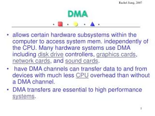
Improving the Data Transfer Speed Between Memory and I/O (or Memory) Direct Memory Access (DMA) • When a system copies information from memory to I/O (e.g., hard disk) or from memory to memory, the information is copied from the source to CPU and then from CPU to the destination • This detour is slow • It occupies the CPU so that CPU cannot work on other things. • DMA is governed by a special controller that is specially designed to move data only • DMA copies data from one memory (or I/O) to another memory (or I/O) without going through CPU • DMA can achieve much faster data transfer rate
Direct Memory Access • DMA is controlled by a special circuitry called DMA controller • DMA controller can control address, data and read/write lines • When CPU is using the bus, DMA cannot start • When DMA is in progress, CPU cannot use the bus • DMA and CPU must negotiate to determine who owns the bus
Direct Memory Access Structure • A DMA controller usually has 5 registers • block length register • source address register • destination address register • byte counter • a temporary data register • A user can initialize the first three registers and start the DMA process
Memory to memory DMA operation 1 Sep up DMA controller Address bus Memory (source) CPU Data bus Control bus Hold Ack Hold Request 2 3 Address bus Memory (dest.) DMA Controller 4-8 Data bus Control bus
Steps in Memory to Memory DMA Operation 1. CPU writes to DMA controller to request a memory to memory DMA operation. 2. DMA starts and requests CPU for buses (Hold Request) 3. CPU gives the buses to DMA (Hold Ack) and disconnects itself from the buses. 4. DMA puts source address and a read signal on address and control buses 5. DMA gets the data from data bus 6. DMA puts destination address, data and a write signal on the buses 7. DMA increments source and destination address registers and byte counter accordingly 8. If the byte counter is not equal to block size, go to step 4; else, DMA gives the buses back to CPU (withdraws Hold Request)
Memory Peripherals to memory DMA operation 1. Set up DMA Address bus Memory (dest.) CPU Data bus Control bus Hold Ack Hold Request 5 2. set up Device 4 7-10 Peripheral Device in DMA mode (source) DMA Controller Data bus Control 3. DMA Request 6. DMA Ack
Steps in peripheral to memory DMA operation • CPU writes to DMA controller to request particular DMA operation. • CPU writes to peripheral device to request particular operation. • When peripheral device is ready with data, it sends a DMA request signal to DMA controller. • DMA controller requests CPU for buses (Hold Request). • CPU gives the buses to DMA (Hold Ack) and disconnects itself from the buses. • DMA controller gives DMA Ack signal back to peripheral device to signal the start of DMA. • DMA sends a read signal to peripheral device and puts the destination address and a write signal on address and control buses for memory. • Data transfers from peripheral to memory directly. • As each byte transferred, the destination address is incremented by 1. • If byte counter is not equal to block size, go to step 6; else, DMA gives the buses back to CPU (withdraws Hold Request)
Performance Issue • When DMA does not work? • CPU spends time to set up DMA • CPU and DMA negotiate the bus usage • So, if the amount of data to be transferred is small, using DMA can actually slow down the system
DMA Example DMA controller registers are accessed in the same way as any other I/O device • Two registers are used for storing the starting address and the word count (or byte count) • The third register contains status and control flags (e.g. R/W determines the direction of the transfer)
DMA Example • When a controller is done transferring a block, it sets the Done flag • Bit 30 is the interrupt enable flag, when set to 1, it causes the controller to raise interrupt after block transfer completion • The controller sets IRQ bit to 1 when it has requested an interrupt • DMA transfer from main memory to the printer • A routine in the Operating System writes the memory addresses, the word count and whether a read or write is to be performed into the registers of the DMA channel assigned to the printer • Whenever the printer is ready, the DMA controller • Sends a read request to the memory • Instructs the printer to get the data from the bus • Then it waits for the printer to be ready again • When the transfer is completed, Done bit is set • Also if the IE bit is set, the DMA controller sends an interrupt request and sets the IRQ
DMA Example • While the DMA transfer is taking place, the program that requested the transfer cannot proceed • However, CPU can execute other programs • The OS is responsible for suspending the execution of one program and starting another • The OS puts the program that requested DMA transfer into the blocked state
DMA Example • Conflict may arise if both CPU and a DMA controller are trying to use the bus at the same time • These conflicts are resolved by a bus arbiter • Memory accesses by the DMA and CPU are interleaved with top priority given to DMA transfers involving synchronous, high speed peripherals • This interleaving is called cycle stealing • Alternatively the DMA controller may be given exclusive access to main memory without interruption. This is called block mode (for a block of memory to be transferred without interruption).
Bus Arbitration • Master: the device that is allowed to initiate data transfers • Only one bus master can exist at any given time • When the master relinquishes control, other devices can become a bus master • The processor is normally the bus master, unless it grants bus mastership to one of the DMA controllers • A DMA controller indicates that it needs to become a master by activating BR (bus request) • BR is the OR of all the bus requests from the devices connected to it
Centralized Arbitration • When BR is active, the processor activates BG1 (bus grant) • BG1 is connected to all the DMA controller in a daisy chain • If DMA1 is requesting the bus, it blocks the bus grant from propagating to other DMAs, otherwise it forwards BG to other DMAs • After receiving the BG, the DMA controller indicates to all devices that it is using the bus by activating BBSY (bus busy), then takes mastership of the bus
Arbitration Example • DMA controller 2 requests and acquires bus mastership • While being a bus master, it can perform one or more data transfers • After it releases the bus, the processor takes bus mastership back
Distributed Arbitration • Each device on the bus is assigned a 4-bit identification number • When one or more devices request the bus, they assert Start-Arbitration and place their 4-bit ID on the lines ARB0 through ARB3 • The code on the four ID lines represent the request that has the highest ID number Wired-NOR becomes Wired-OR
Distributed Arbitration Example Example : Assume A (ID=5) and B (ID=6) are requesting the bus • Device A transmits the pattern 0101 • Device B transmits the pattern 0110 • The arbitration lines are active when low, the code seen by the two devices is 0111 • Each device compares this pattern with its own ID starting with the most significant bit if it detects a difference at any bit position it disables its drivers at that bit position and all lower-order bits • Device A detects a difference on line ARB1 • Thus it disables its drivers on lines ARB1 and ARB0 • The pattern on the arbitration lines changes to 0110 • B wins the contention Wired-OR