Download
1 / 14
140 likes | 145 Views
Date: 2015-05-19. Variable Length Guard Interval for 45 GHz. Authors:. Slide 1. Single carrier (SC) modulation has low PAPR and higher transmitting power efficiency, but requires complicated equalization to combat multipath.

E N D
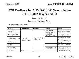
Date: 2015-05-19 Variable Length Guard Interval for 45GHz Authors: Slide 1
Single carrier (SC) modulation has low PAPR and higher transmitting power efficiency, but requires complicated equalization to combat multipath. OFDM modulation offers good performance in multipath environment with simple frequency domain equalization, but suffers from high PAPR and relatively lower transmitting power efficiency. Both single carrier modulation and OFDM modulation are adopted by millimeter wave (mmw) WLAN to balance the advantage and shortcoming of two modulation schemes. SC-Modulation and OFDM-Modulation Slide 2
Traditionally, time-domain equalization (TD-EQ) using complex adaptive filters is used for single carrier system. For mmw communication system, high symbol rate means long adaptive filters even if the channel delay spread is short. When inter-carrier-interference is not severe, simple one-tap frequency-domain equalization (FD-EQ) is sufficient for OFDM system. It is expensive to support both time-domain and frequency-domain equalization and, in general, it desirable to use FD-EQ for both SC and OFDM modulation. Equalization for SC-modulation and OFDM modulation Slide 3
OFDM uses cyclic prefix (CP, also referred as guard interval, GI) to avoid inter-symbol-interference introduce by multipath channel, also maintain frequency orthogonal. OFDM signal structure To enable FD-EQ for SC modulation, similar structure is adopted Signal structure to enable FD-EQ Slide 4
Traditional SC transmitter without CP sends data symbol out immediately once it is generated. SC transmitter with CP has to buffer data symbols to enable the insertion of CP. This introduces latency and increases the complexity of transmitter. Transmitter latency of CP processing Slide 5
Propose using pseudo-random sequence as guard interval for SC modulation The K-length pre-sequence before the M SC symbols can be treated as CP to the K-length post-sequence. M+K=N and N=2m, N point FFT can be used for FD-EQ Pseudo-random sequence is zero correlation zone (ZCZ) sequence [1]. Chip-level π/2-QPSK modulation for pseudo-random sequence Pseudo-random sequence GI for SC modulation Slide 6
Reduced transmitter data processing latency and complexity Receiver performance improvement [1] by utilizing known pseudo-random sequence for more frequent updates of FFT trigger point tracking channel estimation tracking sampling timing offset tracking carrier offset tracking Benefits of Pseudo-random Sequence GI Slide 7
Delay spread can change dramatically in indoor environment. For mmw communication, the delay spread is relative large during the registration to an AP and initial training stages. After the beam forming is activated, the delay spread usually become smaller. Have variable guard interval length can balance the communication performance and efficiency. Variable Guard Interval Length Slide 8
Two guard interval options SC modulation 256-symbol scenario 64 ZCZ sequence and 192 data symbols to form a sub-block 32 ZCZ sequence and 224 data symbols to form a sub-block 512-symbol scenario 128 ZCZ sequence and 384 data symbols to form a sub-block 64 ZCZ sequence and 448 data symbols to form a sub-block OFDM modulation 1/4 and 1/8 CP 1-bit signaling field to indicate the guard interval length Proposed Guard Interval Lengths Slide 9
The ZCZ sequence is designed by the iteration with Discrete Fourier Transform (DFT) matrix and cofficient matrix, based on initial mutually orthogonal aperiodic sequence sets [1]. The chip of ZCZ seuqences is composed by four phase {+1, +j, -1, -j}。The four phases are represented by 0, 1, 2, and 3 in the following sequence definition. The ZCZ sequence of length 32 is 22110220222220132233020222002031 The maximal normalized periodic auto-correlation side lobe peak is 0.3536 ZCZ Sequences (1) Slide 10
The ZCZ sequence of length 64 is 2101000223031311210111130121020021012220230331332101333101212022 The maximal normalized periodic auto-correlation side lobe peak is 0.25 The ZCZ sequence of length 128 is 00112020222220132211022000220213001120201111130200332002113313200011202000000231221102202200203100112020333331200033200233113102 The maximal normalized periodic auto-correlation side lobe peak is 0.3536 ZCZ Sequences (2) Slide 11
Data field structure Slide 12
Propose ZCZ sequence for guard interval of single carrier modulation for lower transmitter latency and improved receiver performance Propose two guard interval length to adapt to delay spread variations Propose 1-bit signaling field to indicate guard interval length Conclusion Slide 13
References [1]. Preamble Sequence for 802.11aj (45GHz) (11-14-1398-01-00aj). Proposal of IEEE802.11aj(45GHz). Slide 14