Download
1 / 13
130 likes | 280 Views
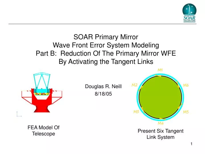
M1. M2. M6. M3. M5. M4. SOAR Primary Mirror Wave Front Error System Modeling Part B: Reduction Of The Primary Mirror WFE By Activating the Tangent Links. Douglas R. Neill 8/18/05. FEA Model Of Telescope. Present Six Tangent Link System. Summary.

E N D
M1 M2 M6 M3 M5 M4 SOAR Primary Mirror Wave Front Error System Modeling Part B: Reduction Of The Primary Mirror WFE By Activating the Tangent Links Douglas R. Neill 8/18/05 FEA Model Of Telescope Present Six Tangent Link System
Summary • Approximately 2/3 of the primary mirror WFE is the result of non equal axial load distribution between the tangent links. • Approximately 1/5 of the primary mirror WFE is the result of the tangent links being overly stiff in bending. This assumes that: • The primary mirror is in its lowest WFE piston, tip and tilt positions. • All the links are initially correctly aligned. • Some of the remaining primary mirror WFE error appears to be the result of distortion of the mirror cell misaligning the tangent links so that they do not lie in the plane perpendicular to the optical axis. The axial force of the misaligned tangent links, produces a force component along the optical axis.
Results 1: Present Configuration • The present primary mirror support configuration produces 3.3 um of astigmatic WFE in the zenith orientation. As demonstrated in the earlier report, for an elevation change over 60 degrees from zenith, an ~ 6 um change in WFE result. BASELINE Present Configuration
Results 2: Existing Tangent Links And Active Tangent Link Load Distribution • In the beam element tangent link model, forces were applied to the tangent links to simulate actuators by equalizing the load carried by the 4 load bearing tangent links. WFE (um) Produced With The Existing Tangent Links Activated. WFE (um) Reduction By Activating The Existing Tangent Links.
Results 3: Perfect Tangent Link Flexures • In the FEA model, the beam element tangent links were replaced by spring element. This configuration simulated perfect flexures that do not transmit moments or torsion. WFE (um) Produced By Perfect Tangent Link Flexure Configuration. WFE (um) Reduction By The Addition Of Perfect Tangent Link Flexure.
Results 4: Perfect Tangent Link Flexures And Active Tangent Link Load Distribution • In the spring element tangent link model, forces were applied to the tangent links to simulate actuators by equalizing the load carried by the 4 load bearing tangent links. WFE (um) Produced By Active Tangent Links With Perfect Flexures. WFE (um) Reduction By Active Tangent Links With Perfect Flexures.
Results 5: Three Perfect Tangent Links • For reference, and to verify the model, the WFE was determined for a configuration with only three links. Each links was represented with spring elements. WFE (um) Produced By Three Perfect Flexure Tangent Links. WFE (um) Reduction By Utilizing Three Perfect Flexure Tangent Links.
Result Summary • All the above figures utilize the same scale (+/- 7.5 um). • All the figures, and their values, are WFE with piston, tip, tilt and focus removed. • Result 3 for is for perfect link flexures without activation, and its figure is not shown. 3.31 um rms Result 1: Present Configuration 1.31 um rmsResult 2: Addition of Perfect Link Actuation 0.63 um rms Result 4: Addition of Perfect Link Flexures 0.28 um rmsResult 5: Reduction from 6 to 3 Links
Conclusion • Proper activation (see Discussion) of the primary mirror tangent links should remove the majority of the primary mirror wave front error. • Non equal link force contribution: ~ 62% • Link bending stiffness contribution: ~ 19% • Link non planar contribution: ~ 19% • Equalizing the forces should also improve the system repeatability (reduce hysterisis) • According to this analysis, the tangent link bending stiffness only contributed 19% of the error, however, this assumes that the primary mirrors piston, tip and tilt are in a configuration that minimized the resulting moments (See Discussion 3).
y x M1 M2 M6 M3 M5 M4 Lateral Link Force Control • The Lateral Link Force Control Loop, will operate only Links 2, 4 and 6, the other 3 links will only be operated to determine M1 position. • Very simple control system • Very stable control system • Quickly converges • Accommodates phantom forces. • The control system must be able to accommodate known phantom forces and moments. • Fxp = The phantom force in the X direction. • Fyp = The phantom force in the Y direction. • Mzp = The phantom moment amount the Z direction. • Phantom Forces will limit the ultimate correction of Lateral Link forces, their cause needs to be better understood, as they might need to be controlled. F2 = F3 F4 = -F1 F6 = F5
y x M1 M2 M6 M3 M5 M4 Forces on Control Loop • Phantom Forces will produce the following Force Errors on the Control Loop: • F1 = Fxp / 2 • F2 = F3 = { Fyp / Cos(30) + (Mzp / R) } / 4 • F4 = - Fxp / 2 • F5 = F6 = { - Fyp / Cos(30) + (Mzp / R) } / 4 • The phantom force in the Y direction (Fyp) is identical to the gravitational force. The force is counteracted equally by the four load carrying tangent links (M2, M3, M5, M6). • The phantom force in the X direction (Fxp) is counteracted by equal forces from the M1 and M4 positioning tangent links. • The phantom moment, about the Z direction, (Mzp) is counteracted equally by the four load carrying links. F2 = F3 F4 = -F1 F6 = F5