Download
1 / 62
740 likes | 1.52k Views
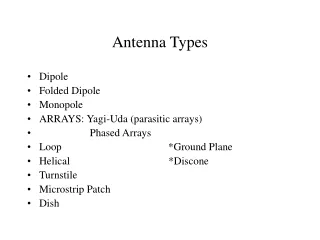
Antenna Types. Dipole Folded Dipole Monopole ARRAYS: Yagi-Uda (parasitic arrays) Phased Arrays Loop *Ground Plane Helical *Discone Turnstile Microstrip Patch

E N D
Antenna Types • Dipole • Folded Dipole • Monopole • ARRAYS: Yagi-Uda (parasitic arrays) • Phased Arrays • Loop *Ground Plane • Helical *Discone • Turnstile • Microstrip Patch • Dish
Monopole Antenna • ¼ wavelength fed at one end • Fed with unbalanced feedline with ground conductor connected to earth ground. • In practice it usually requires an array of radials to develop a better ground plane. (Marconi antenna) • When used at low frequencies the field should be vertically polarized and antenna could be a tower. • The tower is ground insulated and fed at a point above ground with a Gamma match. Z increases upward.
Folded Dipole Antenna • Same length as 1/2 wave dipole • Parallel conductors joined at each end separated by an appropriate spacing. • 300 ohm radiation resistance: Even though current is same magnitude but out of phase with respect to the wire, in SPACE the currents are actually in the same direction due to FOLDING of antenna. • Given the same conditions a dipole and folded dipole radiate the same amount of power. • The current at the feedpoint of the folded dipole is only half the total current.
If the power is the same as the 1/2 wave dipole and current is reduced by half due to folding then feedpoint voltage must be doubled. The result of twice the voltage and half the current is a feedpoint impedance that is four times that of a dipole.
Monopole Antenna • ¼ wavelength fed at one end • Fed with unbalanced feedline with ground conductor connected to earth ground. • In practice it usually requires an array of radials to develop a better ground plane. (Marconi antenna) • When used at low frequencies the field should be vertically polarized and antenna could be a tower. • The tower is ground insulated and fed at a point above ground with a Gamma match. Z increases upward.
Ground Plane Antenna • Can use a COUNTERPOISE system of radials cut to ¼ wavelength to develop ground plane elevated above earth. • If used in a mobile application the roof of the vehicle can serve as a ground plane. • At low frequencies a whip antenna can be used with a loading coil.
Loop Antenna • Typically a receiving antenna. • Uses an air core with radiation in the plane of the loop. • A ferrite core loopstick is also used typically in A.M receivers. • Radiation is in same plane as the loop but broadside to the loopstick • Can also be used as a coil in the R.F. tuned circuit.
5/8th wavelength Antenna • Application as a mobile or base station antenna.. • Omnidirectional response in horizontal plane. • Advantage is realized in the concentration of low angle radiation in horizontal direction. • Does not require as good a ground plane because feedpoint Z at 5/8th wavelength is higher therefore lower current. • Z is lowered to match 50 ohm feedline by matching section.
Helical Antenna • Helix is spiral • An example: ¼ wavelength dipole shortened into helix (rubber ducky) for handheld transeivers. • Typically several wavelengths long and used with a ground plane. • Circumference is ½ wavelength and the turns are ¼ wavelength apart. • Application: VHF satellite transmission. (cross polarization)
Discone Antenna • Widebandth – 10:1 range. • Omnidirectiional in horizontal plane. • Vertically polarized. • Gain is similar to a dipole. Z approaches 50 ohms. • Application: RX scanner antenna for VHF and UHF. • Can also be used for TX.
Parasitic Array – Yagi-Uda • Array antennas can be used to increase directivity. • Parasitic array does not require a direct connection to each element by a feed network. • The parasite elements acquire their excitation from near field coupling by the driven element. • A Yagi-Uda antenna is a linear array of parallel dipoles. • The basic Yagi unit consists of three elements: • 1. Driver or driven element • 2. Reflector • 3. Director
Yagi-Uda Antenna • Develops an endfire radiation pattern. • Optimum spacing for gain of a reflector and driven element is 0.15 to 0.25 wavelengths • Director to director spacings are 0.2 to 0.35 wavelengths apart. • Reflector length is typically 0.5 wavelengths or 1.05 that of the driven element. • The driven element is calculated at resonance without the presence of parasitic elements. • The directors are usually 10 to 20% shorter than at resonance.
Yagi-Uda antennas • Gain is related to boom length and number of directors. • Max directivity of a 3 element Yagi is 9 dBi or 7dBd. • Addition of directors up to 5 or 6 provides significant increase in gain. Addition of more directors has much less impact on gain. • Increasing N from 3 to 4 results in 1 dB increase. • Adding a director to go from 9 to 10 presents a 0.2 dB gain improvement. • Adding more reflectors has minimal impact on gain however does impact on feedpoint Z and the backlobe.
Yagi-Uda • Metal booms can be implemented because voltage is at zero midway through the element. • Other factors that effect resonant lengths: • 1. A comparatively large boom will require parasitic elements to increase their length. • 2. Length to diameter ratio of the elements.
Alpha is the angle of the apex of tapered elements and is typically 30 degrees.
Phased Array Antennas • To be discussed: Monopole Array • Collinear Array • Broadside Array • Endfire Array
Collinear Array • Two or more half wavelength sections. • A broadside array because the axes of the elements are along same line. • Half wave sections are linked by ¼ wave transmission lines. They develop a phase reversal to keep all dipoles in phase. • Usually vertical with an omnidirectional pattern in the horizontal plane with a narrow angle of radiation in the vertical. • What would be a good application for this system?
Multi-Element Broadside and Endfire Arrays • BROADSIDE elements are spaced ½ wavelength apart.(180 degree phase shift. • In order to maintain a broadside presentation of the field the elements are fed out of phase. • ENDFIRE elements are also ½ wavelength apart Elements are fed in phase. • Radiation from all elements sum of the end.
Parabolic Reflector • Gain is a function of parabolic reflector diameter, surface accuracy and illumination of the reflector by the feed mechanism.(focal point) • Optimum illumination occurs when the power at the reflector edge is 10 dB less than at the centre. • F/D ratios of 0.4 to 0.6 will deliver maximum gains. • A collimated beam of radiation will be produced.
Beamwidth f = focal point D = dish diameter D = depth from plane at mouth of dish to vertex.