Download
1 / 22
250 likes | 411 Views
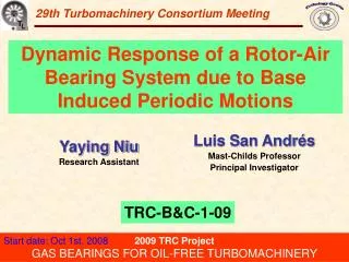
28th Turbomachinery Consortium Meeting. Dynamic Forced Response of a Rotor-Hybrid Gas Bearing System due to Intermittent Shocks. Luis San Andrés Mast-Childs Professor Principal Investigator. Keun Ryu Research Assistant. TRC-B&C-1-08. 2008 TRC Project

E N D
28th Turbomachinery Consortium Meeting Dynamic Forced Response of a Rotor-Hybrid Gas Bearing System due to Intermittent Shocks Luis San Andrés Mast-Childs Professor Principal Investigator Keun Ryu Research Assistant TRC-B&C-1-08 2008 TRC Project GAS BEARINGS FOR OIL-FREE TURBOMACHINERY
Micro Turbomachinery (< 0.5 MW) Flexure pivot Bearing GT 2004-53621 ASME Paper No. GT2002-30404 Gas bearings Gas Foil Bearing • Oil-Free bearing • High rotating speed (DN value>4M) • Simple configuration • Lower friction and power losses • Compact size AIAA-2004-5720-984 ADVANTAGES • High energy density • Compact and fewer parts • Portable and easily sized • Lower pollutant emissions • Low operation cost http://www.grc.nasa.gov/WWW/Oilfree/turbocharger.htm
Gas Bearings for MTM Gas bearings for micro turbomachinery (< 0.5 MW ) must be: Simple – low cost, small geometry, low part count, constructed from common materials, manufactured with elementary methods. Load Tolerant – capable of handling both normal and extreme bearing loads without compromising the integrity of the rotor system. High Rotor Speeds – no specific speed limit (such as DN) restricting shaft sizes. Small Power losses. Good Dynamic Properties – predictable and repeatable stiffness and damping over a wide temperature range. Reliable – capable of operation without significant wear or required maintenance, able to tolerate extended storage and handling without performance degradation. +++Modeling/Analysis (anchored to test data) readily available
Gas Bearings for MTM Thrust in TRC program: Investigate conventional bearings of low cost, easy to manufacture (common materials) and easy to install & align. Combine hybrid (hydrostatic/hydrodynamic) bearings with low cost coating to allow for rub-free operation at start up and shut down Major issues: Little damping, Wear at start & stop, Instability (whirl & hammer), & reliability under shock operation
Bearing shell and Load cells Bearing cover Rig housing Gas bearing Shaft and DC motor Gas bearing test rig Max. operating speed: 100 kpm 3.5 kW (5 Hp) AC integral motor Rotor: length 190 mm, 28.6 mm diameter, weight=0.826 kg Components of high-speed gas bearing test rig
Gas Bearings for MTM GT 2008-50393 2007: Control of bearing stiffness / critical speed Displacements at RB(H) 5.08 bar 2.36 bar 5.08 bar Blue line: Coast down 2.36 bar Red line: Set speed Controller activated system Peak motion at “critical speed” eliminated by controlling supply pressure into bearings
2007-2008 Objectives Demonstrate the rotordynamic performance, reliability, and durability of hybrid gas bearings • Rotor motion measurements for increasing gas feed pressures and speed range to 60 krpm. • Install electromagnetic pusher to deliver impact loads into test rig. • Perform shock loads (e-pusher & lift-drop) tests to assess reliability of gas bearings to withstand intermittent shocks without damage.
TEST gas bearings TEST gas Bearings Flexure Pivot Hybrid Bearings:Promote stability, eliminatepivot wear, engineered product with many commercial applications worn pads surfaces Clearances Cp =38 & 45 mm, Preload =7 & 5 mm (~20%) Web rotational stiffness=20 Nm/rad
2008 Gas Bearing test rig layout E-pusher : Push type solenoid 240 N at 1 inch stroke
Electromagnetic pusher tests Multiple impact Impact duration ~20 ms E-force ~400 N (pk-pk)
Manual lift & drop tests Multiple impact Lift off to 5~15 cm (10~30° rotation)
Coast down: E-pusher tests Ps=5.08 bar (ab) Displacements at LB(H) Intermittent shocks Impact force 100~400 N 46 krpm Shock ~15 g Transient rotor response ~ 40 µm
Coast down: manual lift & drop tests Shock induced acceleration At base 5~20 g At housing 5~10 g Ps=3.72 bar (ab) Beyond critical speed: Synchronous frequency is isolated from shocks Below 20 krpm: Large fluctuation of synchronous response Displacements at LB(H)
Waterfall: manual lift & drop tests Rotor speed decreases Displacements at LB(H) Ps=2.36 bar (ab) Excitation of rotor natural frequency. NOT a rotordynamic instability!
Rotor response: manual lift & drop tests Ps=2.36 bar (ab) Shock loads applied Shock loads applied Overall rotor amplitude increases largely. Subsynchronous amplitudes larger than synchronous
Rotor response: manual lift & drop tests Ps=2.36 bar (ab) Natural frequency of rotor-bearing system(150~190 Hz) Natural frequency of test rig (~40 Hz) Rotor-bearing natural frequency increases with rotor speed. Natural frequency of test rig also excited.
Rotor response: manual lift & drop tests Ps=2.36 bar (ab) 15 krpm Drop induced shocks ~30 g Transient response Full recovery within ~ 0.1 sec.
Rotor speed vs time (No shocks) Dry friction (contact) With feed pressure: long time to coast down demonstrates very low viscous drag!
Rotor speed vs time (Manual lift-drop tests) Overall coast down time reduces with shock loads (~ 20 sec) No shocks Exponential decay (No rubs) even under severe external shocks No shocks
Conclusions • Under shock loads ( up to ~30 g), natural frequency of rotor-bearing system (150-200 Hz) and test rig base (~ 40 Hz) excited. However, rotor transient motions quickly die! • For all feed pressures (2-5 bar), rotor transient responses from shocks restore to their before impact amplitude within 0.1 second. Peak instant amplitudes (do not exceed ~50 µm) • Even under shock impacts, viscous drag effects are dominant, i.e., no contact between the rotor and bearing. • Hybrid bearings demonstrate reliable dynamic performance even withWORN PAD SURFACES
TRC Proposal: Gas Bearings for Oil-Free Turbo-machinery – Identification of Bearing Force Coefficients from Base-Induced Excitations TASKS • Set up an electromagnetic shaker to deliver excitations (periodic loads of varying frequency) to the test rig. • Measure the rotor response due to base induced excitations. • Identify frequency dependent bearing stiffness and damping coefficients from measured rotor transient responses at increasing rotor speeds. • Compare the identified bearing force coefficients to predictions from XLTRC2 computational models. B TRC 2008 /200 9 : UDGET FROM FOR Support for graduate student (20h/week) x $ 1,600 x 12 months, Fringe benefits (2.5%) and medical insurance ($194/month) $ 22,008 Tuition & fees three semesters ($3,996x3) + Supplies for test rig $ 17,992 $ 40,000 Total Cost:
Electromagnetic shaker • Shaker force peak amplitude (sine): 98 N (22 lbf) • Useful frequency range: 5 ~ 9000 Hz LDS V406/8 – PA 100E Operating rotor speed range: 170 Hz ~ 1 kHz 10 krpm ~ 60 krpm Y X Low frequency excitations: simulate road surface effect on MTM Z Identify frequency dependent bearing force coefficients at increasing rotor speeds