Download
1 / 27
270 likes | 495 Views
LED Solder Press. Final Presentation Senior Projects 2 By Ryan Bigl & Kyle Levesque. Background Info. This project is for a small business called LEDDynamics, located in Randolph, Vermont.

E N D
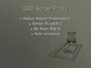
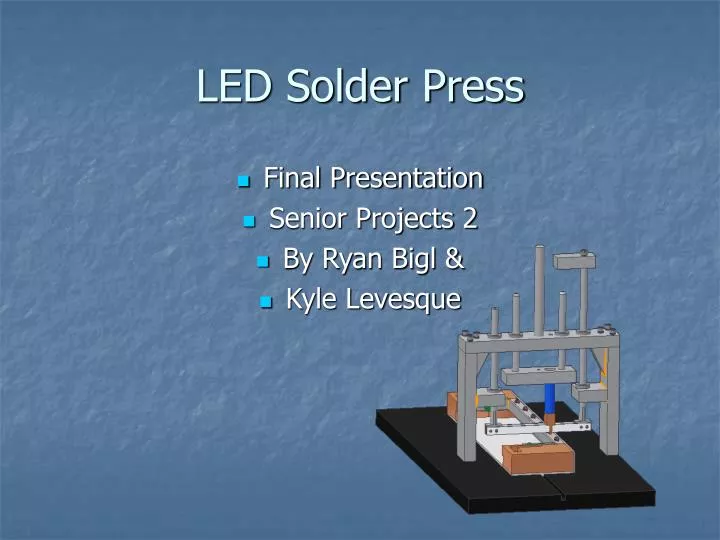
LED Solder Press • Final Presentation • Senior Projects 2 • By Ryan Bigl & • Kyle Levesque
Background Info • This project is for a small business called LEDDynamics, located in Randolph, Vermont. • “LEDDynamics is a custom engineering company specializing in the design and integration of LED technology for end-user and OEM applications.” (From there website: http://www.leddynamics.com)
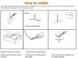
Problem statement Design an automated miniature solder press that will… • Be able to solder pre-glued surface mount LED emitters to a metallic circuit board (MCPCB). • Be able to test the LED after completion. • Must produce better efficiency yield, in comparison to current hand assembly. • System with basic human aid will consistently step through the soldering process.
Solutions • Build a (human controlled) X table with a set jigs for different sized metallic circuit boards. • Make a single press/ dual soldering iron system. • Test the LEDs inline with solder station. • Basic user controls to start and stop the soldering process.
Light Strip Base Sizes • Soldering 2 different strip sizes • Soldering 3 different strip styles
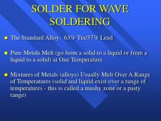
Automated Process Description • Solder iron will come down until LED holder is pressing down on the LED. Heat irons are at set heat point (627 degrees F). • Solder iron will then come down and press fully (40newtons) onto the board and leads for 1.5sec. It will then lift back up to the LED holding position. • The microcontroller will then test LED across the LED holders to see if the soldering process was a success.. • Iron then lifts up full distance to rest position. Microcontroller signals user end of soldering step. If LED was bad Red light will blink.
Full System Overview 120VAC Data lines Air cylinder MCU& Electronics Air lines 12v DC Regulator and oil trap PWM 3way Valve User Interface Jig System
Full System Overview 120VAC Data lines Air cylinder MCU& Electronics Air lines 12v DC Regulator and oil trap PWM 3way Valve User Interface Jig System
Full System Overview 120VAC Data lines Air cylinder MCU& Electronics Air lines 12v DC Regulator and oil trap PWM 3way Valve User Interface Jig System
Fixture System overview • (2) pull pins • (2) springs • Adjustable slide support • (2) rail / receivers • Base plate • Front support plate • (6) 6-32” x ¾”
Pneumatics System Overview • Building air used • Next fed into Oil Trap and Regulator unit • Regulator is set to desired PSI(~65PSI) • Regulated air is then controlled by the MCU in a 12v three way valve unit. • Air from valve is ran into a flow control valve and then into the cylinder. • The cylinder is a 9/16” 3” throw spring returned cylinder with a magnetic piston.
Solder head System Overview • Single solder iron Heater controlled by MCU • LED holders double as Testing leads • Luxeon specified solder iron tip size
Solder head System Overview • Single solder iron Heater controlled by MCU • LED holders double as Testing leads • Luxeon specified solder iron tip size
Solder head System Overview • Single solder iron Heater controlled by MCU • LED holders double as Testing leads • Luxeon specified solder iron tip size
Power and Signal Overview 120VAC P.W.M Heater AC power supply Iron heat sensor Microcontroller AC to DC power supply Red Light Test lead Stop/Go Switch Green Light EStop Triple solenoid block Users control box Cylinder position sensors
State Diagram Concept Power On Heater control Cylinder Control LED Test
State Diagram Concept Power On Power On Heater control Temp check <625oF Turn Heater ON >630oF Turn Heater OFF Cylinder Control <625oF And >630oF Cylinder Control LED Test
State Diagram Concept Jump to Heat Control Has the start been Pressed? Power On Flash Green light .25 Sec Turn Green light on solid Heater control Is the Cylinder Extended Extend Cylinder No Cylinder Control Yes Delay 1.5 Sec LED Test Lift up Part way .5 Sec LED Test
State Diagram Concept Power On Test LED Heater control Is it good? (.7v drop) No (1x) Lift up cylinder Turn on Red light Turn off green light Yes Cylinder Control No (2x) Lift up Cylinder Flash Red light Turn off green light Jump to Heat Control LED Test
Schedule Current status
Summary • Heating— The soldering head and press system has been designed and still needs to be machined. • Mechanical—The fixture and alignment pin system has been designed and built. • Pneumatic—The pneumatic system has been designed, purchased, and tested. • Software—The software has been completed, but still needs wiring.
Project Contacts • Oliver Piluski, LED Dynamics • opiluski@LEDdynamics.com or www.LEDDynamics.com • John Kidder, Senior Projects Teacher • jkidder@vtc.edu • Andre St. Denis, Senior Projects Teacher • ajs05110@vtc.edu • Roger Howes • rhowes@vtc.edu
Questions? • For further information you can access all project web pages at http://web.vtc.edu/ELM/projects/projects_and_teams.htm, or directly link to our website at http://www.vtc.edu/elm/projects/2005-2006/LEDSolderingSystem/WebSite/