Download
1 / 32
320 likes | 329 Views
August 23-28, 2015. New York City, USA. Recent development of plasma optical systems. ICIS - 2015. August 23-28, 2015 New York City, USA. Alexey Goncharov. Institute of Physics NAS of Ukraine, Kiev, 03028, Ukraine. Institute of Physics NAS of Ukraine (Kiev). ICIS - 2015.

E N D
August 23-28, 2015 New York City, USA Recent development of plasma optical systems
ICIS - 2015 August 23-28, 2015 New York City, USA AlexeyGoncharov Institute of Physics NAS of Ukraine, Kiev, 03028, Ukraine Institute of Physics NAS of Ukraine (Kiev)
ICIS - 2015 August 23-28, 2015 New York City, USA ABSTRACT This is the brief review of recent development and ongoing research of plasma optical systems based on the fundamental plasma optical idea magnetic electron isolation, equipotentialization magnetic field line and the axial-symmetric cylindrical electrostatic plasma lens (PL) configuration. The experimental, theoretical and simulation researches have been carried out over recent years collaboratively between IP NASU (Kiev),LBNL (Berkeley,USA) and HCEI RAS (Tomsk). Institute of Physics NAS of Ukraine (Kiev) 3
August 23-28, 2015, New York City, USA • These researches enable detailed description and modeling of plasma-optical systems, as well as prediction of their novel high-technology applications. Here describes in some more detail latest devices for focusing high-current negative charge particle beams and for filtering dense plasma flow from micro droplets. • Outline • Introduction and basic principles • Plasma Devices Based on the Plasma Lens configuration • Plasma Lens with positive space charge • Electron beams focusing by PL with positive space charge cloud • Plasma-Optical Filter For Clearing Micro Droplets • Approach • Experimental set up and conditions • Experimental results • Summary Institute of Physics NAS of Ukraine (Kiev) 4
Indroduction and basic principles August 23-28, 2015 New York City, USA The basic concept of the electrostatic plasma lens is based on the use of magnetically insulated cold electrons (i.e. transverse mobility << parallel mobility) to provide space-charge neutralization of the focused ion beam and maintain the magnetic field lines as equipotentials (“equipotentialization”). This means that value of the magnetic field is those, that the following inequalities are correct ρHe<<R<<ρHi, where ρHe and ρHiare the electron and ion larmor-radiuses, R-typical system size. These early contributions also clarified the advantages of plasma lenses as compared with the more traditional electrostatic lens (of which the Einzel lens is one specific kind) and magnetic lenses. Institute of Physics NAS of Ukraine (Kiev) 5
Indroduction and basic principles August 23-28, 2015 New York City, USA This is a generalization of Gabor’s ideas for employing a magnetized electron cloud in a Penning trap as an effective space charge lens for focusing low current positive ion beams. The condition of equipotential magnetic field lines of length l >> R,, passing through the axial region of the system and crossing the outermost electrodes (which are grounded) follows from a model in which the lens volume is uniformly filled with cold background electrons of density ne and energetic beam ions of density nb= Ib/(eQvbπR2). 6
Indroduction and basic principles August 23-28, 2015 New York City, USA This condition can be given as : where L is the maximum electric potential on the ring electrodes. The plus sign corresponds to beam focusing and the minus sign to beam defocusing − the dispersive operational regime of the lens. Note that the equipotentialization condition follows from the steady-state hydrodynamic equation of motion of cold electrons, which in this case is E = -1/c(vdxB) The macroscopic electrostatic field E can exist only in the presence of closed electron drift and an “insulating” magnetic field. Institute of Physics NAS of Ukraine (Kiev) 8
Indroduction and basic principles August 23-28, 2015 New York City, USA Then the electric field is perpendicular to the magnetic ield, leading to magnetic field lines that are equipotentials. It follows that the self-consistent potential distribution within the lens volume depends on the magnetic field as Φ = kΨ(r,z) Here,Ψ(r,z ) is the magnetic flow function. The lines Ψ(r,z ) = const. are magnetic field lines. A number of effective plasma lenses for positive ion beams focusing were made and tested in collaboration IP NASU and LBNL (Berkeley,USA). See: A.Goncharov, I. Brown, IEEE Trans. Plasma Sci., Vol. 32 (1), 2004, p. 80-83. 9 Institute of Physics NAS of Ukraine (Kiev)
Indroduction and basic principles August 23-28, 2015 New York City, USA Theelectrostaticplasmalensisanaxially-symmetricplasma-opticsdevicewithasetofcylindrical ringelectrodeslocatedwithinthemagneticfieldregion, withfield lines connecting ring electrode pairs symmetrically about the lens midplane; The robust construction, low energy consumption and high cost effectiveness make these tools attractive for applications in high dose implantation facilities, linear heavy ion accelerators, heavy ion fusion and other high technologies. 10 Institute of Physics NAS of Ukraine (Kiev)
Indroduction and fundamental principles 8-11.12.2014 Kottayam, Kerala, India The embodiment of plasma lens used at LBNL: Input aperture 10 cm, length 15 cm, number of cylindrical electrodes 11; magnetic field strength formed by the Fe-Nd-B permanent magnets 300G. Lenses have been used to focus broad (D~10 cm), E 50 keV , high current (hundreds of mA), metal (Bi, Mg, Nb, Ta, Pb…) ion beams with compression factors of ~30-40X 11 Institute of Physics NAS of Ukraine (Kiev)
Indroduction and basic principles August 23-28, 2015 New York City, USA This describes in : 7 Institute of Physics NAS of Ukraine (Kiev)
Plasma Devices Based on the Plasma Lens August 23-28, 2015 New York City, USA The crossed electric and magnetic fields inherent plasma lens configuration provides the attractive method for establishing a stable plasma discharge at low pressure. Using plasma lens configuration in this way several cost-effective, low maintenance, high reliability plasma devices using permanent magnets were developed. In part, it was proposed and created cylindrical plasmaoptical magnetron sputtering device with virtual anodes and target utilization factor up to 100% and cylindrical plasma production device for the ion treatment of substrates with complicated cylindrical shape. These devices can be applied both for fine ion cleaning and activation of substrates before deposition and for sputtering. These plasma tools can be operated as stand-alone plasma devices, or as part of a single technological cycle together with a sputtering system. This describes in : A.A. Goncharov and I.G. Brown “Plasma Devices Based on the Plasma Lens-A Review of Results and Applications” IEEE TPS Vol.35,#.4, 2007,pp.986-991 Institute of Physics NAS of Ukraine (Kiev) 12
Plasma Devices Based on the Plasma Lens August 23-28, 2015 New York City, USA The cross section of cylindrical plasmooptical sputtering device 1-magnetic system,2- target, 3-anode The simplified scheme of cylindrical diode. Institute of Physics NAS of Ukraine (Kiev) 13
Plasma Devices Based on the Plasma Lens August 23-28, 2015 New York City, USA General view of the ion treatment cylindrical plasma device Cut-away view Institute of Physics NAS of Ukraine (Kiev) 14
Plasma Devices Based on the Plasma Lens August 23-28, 2015 New York City, USA One particularly interesting result of this background work was observation of the essential positive potential at the floating substrate treated by cylindrical ion cleaning device. This suggested to us the possibility of an electrostatic plasma lens for focusing and manipulating high-current beams of negatively charged particles, electrons and negative ions, that is based on the use of the cloud of positive space charge in conditions of magnetic insulation electrons. It was proposed to use magnetic electron insulation for creation of a stable positive space charge cloud: Goncharov A., EvsyukovA.,Dobrovol’skii, A Litovko I., Adv. Appl. Plasma Sci., Vol. 6, p. 5-8, 2007. This describes the recent results of investigations the focusing wide aperture intense electron beam by positive space charge plasma lenses based on the ideas of magnetic electron insulation. 16 Institute of Physics NAS of Ukraine (Kiev)
Plasma Lens with Positive Space Charge August 23-28, 2015 New York Simplified schematic of the lens. 1-anode, 2-permanent magnets, 3-magnetic system with cathode This equation systems used for computer simulations. 17 Institute of Physics NAS of Ukraine (Kiev)
August 23-28, 2015 New York City, USA Electron Beam Focusing Experiment Wide aperture plasma electron source: 1 – plasma cathode , 2 – hollow anode, 3 – emission grid, 4 – accelerating electrode. Plasma lens: 5 – permanent magnets, 6 –anode, 7 – cathode. 8 – electron beam, 9,10 – collector rings, 11 – isolators, 12– shield, 13 – slide rod. The beam current is about 100 mA-100A, energy is in a range of 7...25 keV, Electron beam diameter – 6 cm, pulse duration 120 μs. Maximum lens anode potential is 2,5 kV. The lens discharge current is up to 100 mA , Ar pressure 10-5-10-4 Torr. Institute of Physics NAS of Ukraine (Kiev), High Current Electronic Institute SB RAS (Tomsk) 18
Electron Beam Focusing Experiment (Low-current mode) Aug 23-28, 2015 New York Distribution beam curent density along axis.Beam energy - 10 keV, beam current- 200 mA, Magnetic field at the lens center B(0,0) - 50 G, pressur p = 1х10-4 Torr, The lens discharge current-5 mA. Blue curve-current density difference / j(UL=0) — j(UL=2,4 kV)/. Distribution current density at the lens focus. Beam energy - 10 keV, beam current- 200 mA, discharge current- 3 mA, B(0,0)- 50 G, p= 1х10-4 Torr 19 Institute of Physics NAS of Ukraine (Kiev), High Current Electronic Institute SB RAS (Tomsk)
Electron Beam Focusing Experiment (High-current mode) August 23-28, 2015 New York E=16 kV; I=100 A; Н ~ 110 Э 1 - discharge current 2 - beam current before switching on the lens 3 - lens is switched on Beam current – 100 A Energy beam – 16 kV Stainless steel target Imprint of the focused electron beam on the target (size inmm) The discharge in the lens increases stability to the pulse shape of the electron beam current, decreasing its fluctuation amplitude and enhancing the current transport. In experiment the electron beam was compressed from its initial diameter of 6 cm to a diameter of 1 cm; the current density thus increased more than 30 times and was greater than 100 А/cm2 20 IP NASU, Kiev HCEI, Tomsk
Remarks August 23-28, 2015 New York City, USA These first experimental results demonstrate an attractive applications positive space charged PL with magnetic electron insulation for focusing and manipulating wide aperture high-current no relativistic electron beams. For relatively low-current mode for which electron beam space charged less than positive space charged plasma lens it realize electrostatic focusing passing electron beam. This means the effect of E-field exceeds the effect of H- field. In case of high-current mode when electron beam space charge much more than space charge PL the lens operates in plasma mode to create transparent plasma accelerating electrode and compensate space charge propagating electron beam. The lens H- field in this case use for effective focusing beam. Under described experimental conditions the maximal compression factor was up to 30x and beam current density at the focus was about 100 A/cm2. V. Gushenets, A. Goncharov, A. Dobrovolsky, S. Dunets, I. Litovko, E. Oks, A. Bugaev, “IEEE Trans. Plasma Sci”, 41, part.3, 2013, pp.2171-2174. . Institute of Physics NAS of Ukraine (Kiev), High Current Electronic Institute SB RAS (Tomsk) 21
Plasma Lens with Positive Space Charge August 23-28, 2015 New York About focusing negative ion beams I’d like to say a few words about possibility to use PL with positive space charge for focusing negative ion beams. For the first time the attractive perspective to use positive space charge PL to focus negative hydrogen ion beam has been demonstrated by V.Goretsky and I.Soloshenko in: V. Goretskii, I. Soloshenko, A. Shchedrin, Pl.Phys. Rep. Vol. 27(4), 2001. They plainly demonstrated focusing effect by using PL with electrostatic electron isolation. But the presence working gas under pressure of 10-3Torr led to essential losses ion beam. Then authors improved their system by using electron beam as additional ionization factor. This led to decreasing working gas pressure in a few times and decreasing losses focusing beam due to striping by neutral gas. Proposed thin short-focusing lens with using both electrostatic and magnetic electron isolation can provides an essential cloud of positive ions under enough low pressures (about 10-4Torr). So, we are optimistic that lens will work. 16 Institute of Physics NAS of Ukraine (Kiev)
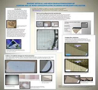
Aug 23-28, 2015 New York Plasma-Optical Filter For Clearing Micro Droplets. Approach We propose new approach for devise a novel plasma technology for the filtering of microdroplets (or their reduction to the nanoscale) from the dense metal plasma flow formed by erosion plasma sources (vacuum arc and laser produced plasma sources), without loss of plasma production efficiency. This approach is based on application a cylindrical electrostatic plasma lens located along the axis of the plasma flow. An electron stream is created within the plasma lens formed near internal cylindrical surface and injected along radius towards the axis. The theoretical estimations have shown the energy of these electrons to be sufficient to eliminate the micro-droplets. Institute of Physics NAS of Ukraine (Kiev) 22
Aug 23-28, 2015 New York Plasma-Optical Filter For Clearing Micro Droplets. These results were presented and discussed preliminary at the SVC conference at Santa Clara, USA, CA, at May 2012. Goncharov, V. Maslov and A. Fisk, 55th Annual Technical Conference Proceedings, Santa Clara, CA April 28–May 3, 2012, p.441-444 See also: Andrew Fisk, VasiliyMaslov, AlexeyGoncharov, United States. Patent Appl Publication # 2014/0034484A1 Feb.6,2014 “Device for the Elimination of Microdroplets from a Cathodic Arc Plasma Source” Institute of Physics NAS of Ukraine (Kiev) 23
Plasma-Optical Filter For Clearing Micro Droplets. Aug 23-28, 2015 New York beam beam Area of secondary electron emission The simplified scheme of evaporation drops of a vacuum arc plasma flow. C - cathode, A - anode, D - aperture, MS - the magnetic system, M - the magnetic field lines, Δ is the spatial layer, in which the strong radial electrical field is supported, C1 is the hollow cylinder, from which internal surface there is a secondary electron emission under action of the accelerated ion flow 24 Institute of Physics NAS of Ukraine (Kiev) MS M Substrate D C A C1
Plasma-Optical Filter For Clearing Micro Droplets. Aug 23-28, 2015 New York The application of a negative potential can leads to the formation of a spatial layer Δ<<ρe≡eEr/meωHe2 with a large electrical field Er near cylindrical electrode C1 . This field is mainly directed toward the radius. Note, the system is in a magnetic field which must satisfy the following inequalities: ρHe<<D<<ρHi, Here ρHeand ρHi are the electron and ion Larmour radiuses. In this magnetic field the electrons are magnetized and ions are not magnetized. The calculations show the energy of the formatting by second ion-electron emision electron beam enough for micro droplet elimination during propagating plasma flow through plasma-optical filter. 25 Institute of Physics NAS of Ukraine (Kiev), High Current Electronic Institute SB RAS (Tomsk)
Plasma-Optical Filter For Clearing Micro Droplets. Aug 23-28, 2015 New York Experimental Set Up In order to test, check and investigate the idea of plasma-optical droplet filter was assembled the experimental set up shown at the Figure. 26 Institute of Physics NAS of Ukraine (Kyiv)
Plasma-Optical Filter For Clearing Micro Droplets. Aug 23-28, 2015 New York Experimental Conditions • DC discharge arc current:60A. • •Discharge voltage: 22 V at H= 0 Gauss • •Discharge voltage: 30 V at H =360 Guass • •Substrate Bias=-200V. • •Substrate area: 1 cm2 • •Deposition time: 3 min. • •Distance between substrate and target: 250 mm. • •Сathode diameter (Cu): 20 mm. The main parameters of plasma optic system is: Magnetic field created by permanent magnets about 360Gs at axis. Voltage at central lens electrode up to -1-1,5 kV. Outmost electrodes are grounded. Lens aperture about 7 cm Length 15 cm 27 Institute of Physics NAS of Ukraine (Kiev)
Plasma-Optical Filter For Clearing Micro Droplets. Aug 23-28, 2015 New York Experimental Results SEM photo of copper microdroplets B=0 G, U=0 V. Ion current 4 mA (square of images 250 μm x330 μm) 28 Institute of Physics NAS of Ukraine (Kiev)
Plasma-Optical Filter For Clearing Micro Droplets. Aug 23-28, 2015 New York Experimental Results SEM photo of copper microdroplets B=360 G, U= -900 V. Ion current-30mA 29 Institute of Physics NAS of Ukraine (Kiev)
Plasma-Optical Filter For Clearing Micro Droplets. Aug 23-28, 2015 New York These first experiments and theoretical estimations demonstrate the workability an idea application new plasma-optical system with a convergent and oscillating fast electrons for effective additional evaporation and destroying of liquid metal droplets in a flow of dense metal plasma formed by erosion plasma sources. The work is in progress. It need some time to study all physical peculiarities processes creation, introduction and interaction fast electrons with propagating through plasma guide flow of the metal plasma to optimized requirements for fabrication new generation high effective and low cost droplet filters. Summary 30 Institute of Physics NAS of Ukraine (Kiev)
Summary Plasma-Optical Filter For Clearing Micro Droplets. Aug 23-28, 2015 New York It should be note, that we have obtained interesting results recently in the HCE Institute where studied repetitively pulsed MEVVA ion-plasma source with plasma optical filter. The first experiments demonstrate that smallest droplets are most affected by the electron beam impact. Perhaps, this is due to difference times-of –flight for different micro droplets. At last,it would be interesting to study potential possibility to use these oscillating fast electrons for enhancement ion state charge distribution in MEVVA kind ion sources.