Download
1 / 14
340 likes | 1.21k Views
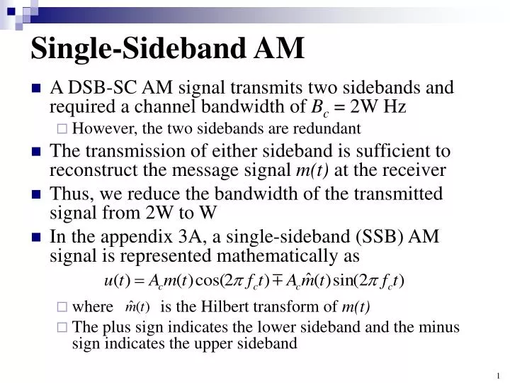
Single-Sideband AM. A DSB-SC AM signal transmits two sidebands and required a channel bandwidth of B c = 2W Hz However, the two sidebands are redundant The transmission of either sideband is sufficient to reconstruct the message signal m(t) at the receiver

E N D
Single-Sideband AM • A DSB-SC AM signal transmits two sidebands and required a channel bandwidth of Bc= 2W Hz • However, the two sidebands are redundant • The transmission of either sideband is sufficient to reconstruct the message signal m(t) at the receiver • Thus, we reduce the bandwidth of the transmitted signal from 2W to W • In the appendix 3A, a single-sideband (SSB) AM signal is represented mathematically as • where is the Hilbert transform of m(t) • The plus sign indicates the lower sideband and the minus sign indicates the upper sideband
APPENDIX 3A: DERIVATION OF THE EXPRESSION FOR SSB-AM SIGNALS • Let m(t) be a signal with the Fourier transform M(f) • An upper single-sideband amplitude-modulated signal (USSB AM) is obtained by eliminating the lower sideband of a DSB AM signal • Suppose we eliminate the lower sideband of the DSB AM signal, uDSB( t ) = 2Acm(t)cos 2fct, by passing it through a highpass filter whose transfer function is given by • H(f) can be written as • where u-1(.) represents the unit-step function
APPENDIX 3A: DERIVATION OF THE EXPRESSION FOR SSB-AM SIGNALS • Therefore, the spectrum of the USSB-AM signal is given by • Taking the inverse Fourier transform of both sides and using the modulation and convolution properties of the Fourier transform, we obtain • Next, we note that • From Eq (2.3.12) and the duality theorem of the FT
APPENDIX 3A: DERIVATION OF THE EXPRESSION FOR SSB-AM SIGNALS • Nowwe obtain • where we use the identities • Then we obtain • which is the time-domain representation of a USSB-AM signal.
APPENDIX 3A: DERIVATION OF THE EXPRESSION FOR SSB-AM SIGNALS • The expression for the LSSB-AM signal can be derived by noting that • Therefore • Thus, the time-domain representation of a SSB-AM signal can generally be expressed as • where the minus sign corresponds to the USSB-AM signal, and the plus sign corresponds to the LSSB-AM signal
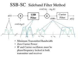
Single-Sideband AM • The SSB-AM signal u(t) may be generated by using the system configuration as shown in right. (Generation of a lower SSB-AM) • Another method (“filter method”) generates a DSB AM signal and then employs a filter that selects either the upper sideband or the lower sideband of the DSB AM.
Demodulation of SSB-AM Signals • To recover the message signal m(t) in the received SSB-AM signal, we require a phase-coherent or synchronous demodulator • For the USSB signal • By passing the product signal in above equation through an lowpass filter, the double-frequency components are eliminated. Then • Note that the phase offset not only reduces the amplitude of the desired signal m(t) by cos, but it also results in an undesirable sideband signal due to the presence of in yl(t) • The latter term was not present in the demodulation of a DSBSC signal • It contributes to the distortion of the demodulated SSB signal
Demodulation of SSB-AM Signals • The transmission of a pilot tone at the carrier frequency is a very effective for providing a phase-coherent reference signal • However, a portion of the transmitted power must be allocated to the transmission of the carrier • The spectral efficiency of SSB AM is very attractive in voice communications over telephone channels • “Filter method”,which selects one of the two signal sidebands for transmission, is difficult to implement when the message signal m(t) has a large power concentrated around f = 0 • In such a case, the sideband filter must have an extremely sharp cutoff around the carrier in order to reject the sideband • Such filter characteristics are very difficult to implement in practice
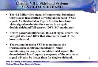
Vestigial-Sideband AM • The stringent-frequency response requirements on the sideband filter in an SSB-AM system can be relaxed by allowing vestige, which is a portion of the unwanted sideband, to appear at the output of the modulator • Thus, we simplify the design of the sideband filter at the cost of a small increase in the channel bandwidth required to transmit the signal • The resulting signal is called vestigial-sideband (VSB) AM • This type of modulation is appropriate for signals that have a strong low-frequency component, such as video signals • That is why this type of modulation is used in standard TV broadcasting
Vestigial-Sideband AM • To generate a VSB-AM signal, we generate a DSB-SC AM signal and pass it through a sideband filter with the frequency response H( f ), as shown in below • In the time domain, the VSB signal may be expressed as • where h(t) is the impulse response of the VSB filter • In the frequency domain, the corresponding expression is (eq. 1) Generation of vestigial-sideband AM signal.
Vestigial-Sideband AM • To determine the frequency-response characteristics of the filter, we will consider the demodulation of the VSB signal u(t). • We multiply u(t) by the carrier component cos2fctand pass the result through an ideal lowpass filter, as shown in below. • Thus, the product signal is or Demodulation of VSB signal.
Vestigial-Sideband AM • If we substitute U( f ) from eq. (1) into V(f), we obtain • The lowpass filter rejects the double-frequency terms and passes only the components in the frequency range | f|W • Hence, the signal spectrum at the output of the ideal lowpass filter is • The message signal at the output of the lowpass filter must be undistorted • Hence, the VSB-filter characteristic must satisfy the condition
Vestigial-Sideband AM • We note that H(f) selects the upper sideband and a vestige of the lower sideband • It has odd symmetry about the carrier frequency fcin the frequency range fc- fa< f < fc+ fa, where faisa conveniently selected frequency that is some small fraction of W, i.e., fa<< W • Thus, we obtain an undistorted version of the transmitted signal VSB-filter characteristics.
Vestigial-Sideband AM • The frequency response of a VSB filter that selects the lower sideband and a vestige of the upper sideband is shown in below • In practice, the VSB filter is designed to have some specified phase characteristic • To avoid distortion of the message signal, VSB filter should have a linear phase over its passband fc- fa | f | fc + W Frequency response of the VSB filter for selecting the lower sideband of the message signals.