Download
1 / 47
470 likes | 729 Views
TORA! TORA! TORA!. By Jansen Cohoon. Developing TORA. TORA was funded by the Army Research Laboratory. TORA is presently being transitioned into the commercial sector by several companies. Boeing, Telecordia, NOVA Engineering and the National Science Foundation. Charac-TORA-istics.

E N D
TORA! TORA! TORA! By Jansen Cohoon
Developing TORA • TORA was funded by the Army Research Laboratory. • TORA is presently being transitioned into the commercial sector by several companies. • Boeing, Telecordia, NOVA Engineering and the National Science Foundation.
Charac-TORA-istics • Temporally Ordered Routing Algorithm • Use of Non-Shortest Path • On Demand Routing • Link Reversal Routing Family • Nodes Maintain One Hop Knowledge
Charac-TORA-istics • Highly Adaptable • Multiple Routes • Network Partition Detection • Destination Oriented • Directed Acyclic Graph
Modeling TORA • Network is modeled after a graph: G=(N,L) N is a finite set of nodes. L is the set of links or edges. • Each node has an ID. • Nodes make use of omni directional antenas
The 3 Routes of TORA • Route Creation: Establishing a set of directed links from the source to destination. • Route Maintenance: Changes in topology cause routes to be reestablished. • Route Erasure: Upon partition detection routes are removed.
Controlling TORA • Three Control Packets: • Query (QRY) flooded through network to establish routes. • Update (UPD) propagates back if route exists and re-orient route structure • Clear (CLR) flooded through network to erase invalid routes.
How High is TORA? • TORA maintains its DAG by a quintuple. • H = (t, oid, r, d, i) • H = Height • t = time • oid = orignating node ID • r = reflection bit; 0 = original, 1 = reflected • d = ordering integer • i = nodes ID
Still High on TORA • The height of the nodes determines the path for a given destination. • The destination has a height (0,0,0,0,dest). • If the nodes are kept in order the data will flow downstream to the destination. • (t, oid, r) is the reference level. • (d, i) is the offset
Route Creation • A node will create a route if it has no downstream neighbors to the destination. • It will the set is Route Required (RR) flag and broadcast a QRY packet. • The QRY packet contains the destination node. • An UPD packet will be used to reply.
Upon Receiving a QRY • IF RR flag is set, does not forward and discard QRY packet. • IF RR flag not set and has no downstream neighbors, it sets RR and rebroadcasts QRY. • If node has at least 1 downstream neighbor and the height for that link is NULL (-,-,-,-,i) it sets its height to the minimum of its neighbors, increments its d value and broadcasts an update.
Upon Receiving a QRY Continued. • If the node has a downstream neighbor and its height is non-Null and the RR flag is set. It will discard the UPD packet. If the RR flag is not set it will send an update packet.
Upon Receiving an UPD • If the reflection bit of the neighbors height is not set and its route required flag is set it sets its height for the destination to that of its neighbors but increments d by one. It then deletes the RR flag and sends an UPD message to the neighbors, so they may route through it.
Upon Receiving an UPD Continued. • If the neighbors route is not valid or the RR flag was unset, the node only updates the entry of the neighbors node in its table.
Maintenance Cases: 1 • 1 Generate: The node has lost its last downstream link due to a failure. The node defines a new "reference level", so it sets oid (originator id) to its node id and t to the time of the failure. This is done only if the node has upstream neighbors. If not it sets its height to NULL.
Maintenance Cases: 2 • 2 Propagate: The node has no more downstream link due to a link reversal following the receipt of an update packet and the reference levels (t,oid,r) of its neighbors are not equal. The node then propagates the references level of its highest neighbor and sets the offset to a value which is lower (-1) than the offset of all its neighbors with the maximum level.
Maintenance Cases: 3 • 3 Reflect: The node has lost its downstream links due to a link reversal following the receipt of an update packet and the reference heights of the neighbors of the node are equal with the reflection bit not set. The node then reflects back the reference height by setting the reflection bit. It's d value is set to 0.
Maintenance Cases: 4 • 4 Detect: The node has lost its downstream links due to a link reversal following the receipt of an update packet and the reference heights of the neighbors of the node are equal with the reflection bit set. This means that the node has detected a partition and begins the route erasure procedure. The height values are set to NULL.
Maintenance Cases: 5 • 5 Generate: The node has lost its last downstream link due to a link reversal following the receipt of an update packet and the reference heights of all the neighbors are equal with the reflection bit set and the oid of the neighbors heights isn't the node's id. The node then sets t to the time of the link failure and sets oid to its own id. The d value is set to 0. This means that the link failure required no reaction. The node experienced a link failure between the time it propagated a higher reference (from someone else) and the time this level got reflected from a place further away in the network. Because the node didn't define the new reference level itself this is not necessarily an indication of a partitioning of the network. So the node simply defines a new higher reference level with the time of the link failure.
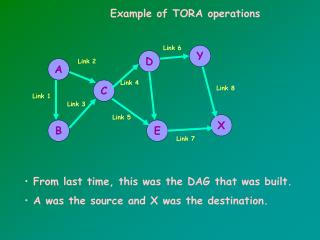
Network Partition and Route Erasure F to G fails, partitioning G from the rest of the network
Network Partition and Route Erasure F starts a new reference level, and sends UPD with with oid=F and t = time of link failure
Network Partition and Route Erasure The links D-F and E-F reverse. Node D propagates the reference level.
Network Partition and Route Erasure E “reflects” reference level from F. Reference heights of the neighborsare equal with the reflection bit not set. E sets the reflection bit and sets offset to 0. Node C propagates new reference level.
Network Partition and Route Erasure Node A propagates reference level.
Network Partition and Route Erasure Node B reflects the reference level, because all of its neighbors have the same reference height and their reflection bits are not set. The offset is set to 0 to make node B now be higher than its neighbors and the reflection bit is set.
Network Partition and Route Erasure Links are now reversed in the opposite direction, but the reflection bit is set.
Network Partition and Route Erasure Node D propagates the reference level the reference heights of the neighbors of F are equal, but the reflection bit is set. F has detected a partition and sets its height to NULL indicating that the route to the destination no longer exists. The route erase protocol is triggered.
Route Erasure • When a node has detected a partition it sets its height and the heights of all its neighbors for the destination in its table to NULL and it issues a CLR packet. The CLR packet consists of the reflected reference level (t,oid,1) and the destination id. • If a node receives a CLR packet and the reference level matches its own reference level it sets all heights of the neighbors and its own for the destination to NULL and broadcasts the CLR packet. If the reference level doesn't match its own it just sets the heights of the neighbors its table matching the reflected reference level to NULL and updates their link status (->undirected).
Conclusion • TORA is GREAT for MANET! • It is very applicable to Tactical Networks.
References • L. P. Burka, “Temporally Ordered Routing Algorithm,” SECAN-LAB, http://wiki.uni.lu/secan-lab/Temporally-Ordered+Routing+Algorithm. (current Feb. 21, 2005). • Vincent D. Parka and M. Scott Corson, ” A Highly Adaptive Distributed Routing Algorithm for Mobile Wireless Networks,” Naval Research Laboratory, 1997.