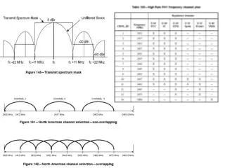
Download
1 / 15
150 likes | 353 Views
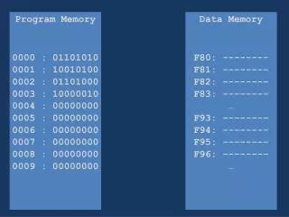
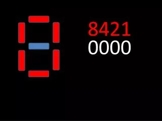
0000. 13. 0001. 01. 0002. 30. 0003. 21. 01. 30. 0004. 01. 0005. 31. 0006. 12. 00. 00. 13. 0000. 13. 01. 30. 21. 01. 31. 12. 00. 00. 13.

E N D
0000 13 0001 01 0002 30 0003 21 01 30 0004 01 0005 31 0006 12 00 00 13
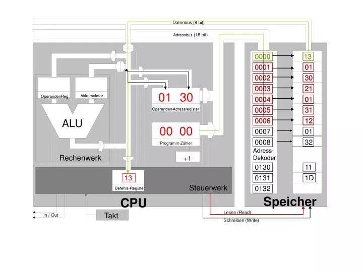
0000 13 01 30 21 01 31 12 00 00 13 Programmzähler-> 0000 -> „Wähle Speicherzelle 0000“ Leseleitung wird aktiviert, „13“ wird im Befehlsregister abgelegt. „LOAD ACCU“
0001 01 01 00 00 01 13 PZ +1 0001 lese Speicherz. 0001 „01“ wird als MSB Operandenteil ins Operandenregister übernommen.
0002 30 01 30 00 02 01 13 PZ+1 0002 lese Speicherzelle 0002, “30“ wird als LSB Operandenteil ins Operandenregister gespeichert.
11 01 30 0130 11 13 Befehlfsregister 0130 lese Adresse „0130“, Inhalt „11“ wird an den Akkumulator geschickt - Befehl „LOAD ACCU“ abgeschlossen
11 0003 21 00 02 03 21 PZ+1 0003 lese Speicherzelle 0003 Inhalt 21 wird an Befehls-register gegeben Operationscode 21 = „LOAD ACCU“
11 01 0004 01 00 04 03 21 PZ+1 0004 lese Speicherzelle 0004, Inhalt „01“ wird als MSB-Operandenteil ins Operandenregister geschrieben
11 01 31 0005 31 00 05 04 21 PZ+1 0005 lese Speicherzelle 0005, Inhalt „31“ wird als LSB-Operandenteil ins Operandenregister geschrieben
1D 11 01 31 00 05 21 0131 1D Operandenregister 0131 lese Speicherz. „0131“, Inhalt „1D“ wird an den Akkumulator geschickt
1D 11 2E 0006 12 00 05 06 21 12 der ALU wird die Funktion Addieren mitgeteilt „12“, Die Summe von „1D“ und “2E“ wird errechnet, ausgegeben und in den Akkumulator geschrieben
1D 2E 01 00 06 07 0007 01 12 Anweisung „STORE ACCU“ PZ+1 (0007) lese Speicherzelle 0007, der Inhalt „01“ wird als 1ster Teil in das Operandenregister geschrieben
1D 2E 01 32 00 07 08 0008 32 12 PZ+1 (0008) lese Speicherzelle 0008, der Inhalt „32“ wird als 2ter Teil in das Operandenregister geschrieben
1D 2E 01 32 00 08 12 0132 2E Operandenregister 0132 Speicherzelle „0132“, Inhalt „2E“ des Akkumulators gelangt in Datenbus, Schreibleitung wird aktiviert • Ergebniss “2E“ wird in Speicherzelle 0132 geschrieben - Befehl „STORE ACCU“ ist abgeschlossen