Download

1 / 18
220 likes | 471 Views
Unit 11 Latches and Flip-Flops. Ku-Yaw Chang canseco@mail.dyu.edu.tw Assistant Professor, Department of Computer Science and Information Engineering Da-Yeh University. Outline. 11.1 Introduction 11.2 Set-Reset Latch 11.3 Gated D Latch 11.4 Edge-Triggered D Flip-Flop 11.5 S-R Flip-Flop

E N D
Unit 11Latches and Flip-Flops Ku-Yaw Chang canseco@mail.dyu.edu.tw Assistant Professor, Department of Computer Science and Information Engineering Da-Yeh University
Outline 11.1 Introduction 11.2 Set-Reset Latch 11.3 Gated D Latch 11.4 Edge-Triggered D Flip-Flop 11.5 S-R Flip-Flop 11.6 J-K Flip-Flop 11.7 T Flip-Flop 11.8 Flip-Flops with Additional Inputs 11.9 Summary Latches and Flip-flops
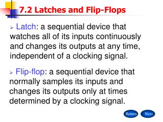
Introduction • Sequential switching circuits • The output depends on • Present input • Past sequence of inputs • ‘remember’ something about the past history of the inputs • Two commonly used memory devices in sequential circuits • Latches – no clock input • Flip-flops Latches and Flip-flops
Feedback • The output of one of the gates is connected back into the input of another gate in the circuit so as to form a closed loop. • The rate at which the circuit oscillates is determined by the propagation delay in the inverter. Latches and Flip-flops
Two Inverters witha Feedback Loop • Two stable conditions • Often referred to as stable states Latches and Flip-flops
Outline 11.1 Introduction 11.2 Set-Reset Latch 11.3 Gated D Latch 11.4 Edge-Triggered D Flip-Flop 11.5 S-R Flip-Flop 11.6 J-K Flip-Flop 11.7 T Flip-Flop 11.8 Flip-Flops with Additional Inputs 11.9 Summary Latches and Flip-flops
Set-Reset Latch • Introduce feedback into a NOR-gate circuit • S=R=0 is a stable condition • S=1 and R=0 is a stable condition Latches and Flip-flops
Set-Reset Latch Latches and Flip-flops
Set-Reset Latch • This circuit is said to have memory because its output depends not only on the present inputs, but also on the past sequence of inputs. Latches and Flip-flops
Set-Reset Latch • R = S = 1 is not allowed • The outputs P and Q are always complements, that is, P = Q’. • The circuit is in cross-coupled form. Latches and Flip-flops
Set-Reset Latch • An input S = 1 sets the output to Q = 1 • An input R = 1 resets the output to Q = 0 • R and S cannot be 1 simultaneously Latches and Flip-flops
Improper S-R Latch Operation • The latch may continue to oscillate if the gate delays are equal. Latches and Flip-flops
Timing Diagram Latches and Flip-flops
S-R Latch Operation Latches and Flip-flops
Map and Equation of the Latch • Next-state equation, or characteristic equation • Q+ = S + R’ Q (SR=0) Latches and Flip-flops
S-R Latch Applications • Components in more complex latches and flip-flops • Debouncing switching Latches and Flip-flops
S-R Latch • An alternative form of the S-R latch uses NAND gates Latches and Flip-flops
S-R Latch • S = 0 will set Q to 1 • R = 0 will set Q to 0 • S = R = 0 is not allowed Latches and Flip-flops