Download
1 / 42
420 likes | 547 Views
Design of a Control Workstation for Controller Algorithm Testing. Aaron Mahaffey Dave Tastsides Dr. Dempsey. Presentation Preview. Project Summary and Objective Hardware Controller Application DC Motor Model Power Amplifier F/V Converter Modeling Summer Circuit

E N D
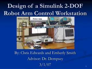
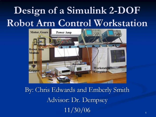
Design of a Control Workstation for Controller Algorithm Testing Aaron Mahaffey Dave Tastsides Dr. Dempsey
Presentation Preview • Project Summary and Objective • Hardware Controller Application • DC Motor Model • Power Amplifier • F/V Converter Modeling • Summer Circuit • Hardware Controller Design • Experimental Results
Presentation Preview • Software Controller Application • Level Shifting Circuit • BSP/Core Functions • User Interface • Command Signal • Sampling Period • Summer • F/V Converter • Digital Controller • Digital Controller Results
Presentation Preview • Demonstration Work • Final Parts List • Future Project Work
Project Summary • Design of a control workstation to test control algorithms for a Pittman DC motor • Provide insight to classical and digital control system theory through practical applications • First apply control system with all hardware components, then implement as much as possible into software
Project Summary • Quansar Consulting currently develops control workstations for $5,000 • Each station requires a PC with an internal A/D and D/A converter • Goal is to develop a system at a much lower cost of $400 based on the 8051 development board
Motor Model Gp(s) = 1949166 _ s2 + 920s + 114133 • Poles at s= -148 and s= -772 rad/sec • DC Gain of 17.08
Power Amplifier • Discrete Component Design • Internal Controller for Stability • Passive Lag Network • Internal Feedback Loop • Open Loop Crossover Distortion • ±27.5 Volt Output Range
Power Amplifier Model • Closed Loop Gain = 11 • Results from Matlab after observing open loop frequency response in PSpice: • Time Constant = 10 us • Pole = 628000 rad/sec • G(s) = 11 _ s/628000 + 1
F/V Converter Modeling • Desire Output of 2.5 V for Maximum RPM of 762 • 762 RPM Corresponds to 38.4 kHz • Desired Gain = 2.5/38400 = .0000652 • Experimentally Measured Results: • Time Delay = 5 ms • Pole at 388 rad/sec
F/V Converter Modeling G(s) = .0000652*e-.005s s/388 + 1
Summer Circuit • Produces Error Signal from Difference of Command and Feedback Signals • Design using LF412 Operational Amplifier and precision resistors. • Experimental Transfer Function • Vo = .9945V1 - .9895V2
Hardware System Controller • Motor Tracking System • Motor shaft velocity follows analog command signal • All subsystems designed with hardware • Drive up to 762 RPM in positive direction • Command signal of 0 - 2.5 volts • Controller Phase Margin of 60º • Steady State Error of zero (integrator)
Hardware Controller Design • PI Controller • Proportional Gain • Locates necessary crossover frequency to meet 60º phase margin specification • Obtained using Frequency Domain Design • Integrator • Drives Steady State Error to zero
Hardware Controller Design • Design for crossover frequency and adjust gain to get correct PM • Final Frequency Design Results from Matlab: • K = 37.6 • PM = 59.6º • wc = 34 rad/sec • Overshoot = 7.06 %
Experimental Results • Experimental Overshoot = 33 % • Why such a large deviation? • D/A phase lag • Sampling Period (T) = 2 ms • Phase lag = -wcT = -3.5 º • Motor and F/V time delay • Added time delay = 6.1 ms • Phase lag = -wcTd = -11 º
Experimental Results • Experimental Gain = 40 • Could account for -5º phase lag • New phase margin = 40.5º • New expected overshoot = 26 % • New deviation = 7 %
Presentation Preview • Software Controller Application • Level Shifting Circuit • BSP/Core Functions • User Interface • Command Signal • Sampling Period • Summer • F/V Converter • Digital PI Controller • Digital Controller Results
Level Shifting Circuit • In all applications, a signal is sent from the EMAC D/A Converter • D/A Converter Output is 0-5 Volts • Desired Signal is ±2.5 Volts for Bidirectional Drive in Software Application • D/A Converter Output must be shifted by -2.5 Volts
Board Support Package (BSP) • Supports all Devices on Board • Timer 0 • Timer 2 • D/A converter • A/D converter • Keypad • LCD
Core • Contains Functions Common in all Applications • Summer • Conversion routines • RPM measurement • F/V calculation
User Interface • Communicates with User • Ask for sampling period • Ask for Proportional Gain • Ask if Integration Desired • Ask for step magnitude (+ or -) • Verify all entries • Display current motor RPM
Command Signal • Command Signal • Magnitude and sign provided by user interface routine • Value entered is level shifted • Value is written to the D/A: • 0 – 2.5 Volts -> Negative • 2.5 – 5 Volts -> Positive • Support for step inputs only
Sampling Period • Sampling Period • Entered by user in terms of microseconds • Value is converted to a timer reload value • Timer 0 is setup with calculated reload value • All sample driven functions are called from Timer 0 interrupt service routine
Summer • Summer • Subtracts value of F/V converter feedback signal from command signal • Software version allows for bidirectional error signal by determining motor direction from encoder signals • Called at sampling rate by Timer 0 interrupt service routine
F/V Converter • Timer 2 initialized to auto reload on negative encoder transition and capture on positive transition • Capture value in timer 2 registers holds cycles per encoder pulse width • RPM and F/V output calculated from measured pulse width • Continuously measures pulse width, but calculation occurs once every sampling rate
Digital P/PI Controller • Proportional gain entered by user in 1/255 increments • User chooses between P or PI control • Integrator mapped in software as: Z _ Z - 1
Digital Controller Results • For Simulated K = 1 • Overshoot = 15.15% • tp ≈ 55 ms • For Experimental K = 1 • Overshoot = 16.4% • tp ≈ 60 ms • For Simulated/Experimental K = 0.2 • No overshoot • For Simulated/Experimental K = 5 • Unstable
Demonstration Work • Model wheel loader demonstrates effectiveness of controller • DC generator shaft connected to controlled motor shaft provides voltage to power wheel loader motor • Moving bucket arm creates a variable load on the generator
Demonstration Work • Controller maintains constant motor velocity • DC generator maintains constant voltage • Bucket arm velocity remains constant for moderately varying loads
Demonstration Work • Separate EMAC controls bucket arm movement • Two different operation modes • Auto - bucket arm moves up and down continuously one second at a time • Manual - pressing and holding buttons on keypad moves bucket arm
Final Parts List • Pittman DC Motor • 2 x GM9236C534-R2 • EMAC x 2 • Operational Amplifiers • 2 x LF412 • Transistors • 2 x TIP30 • 4 x TIP31
Final Parts List • Diodes • 2 x 1N5617 • D Flip-Flop • 7474
Future Project Work • Implement more complex controllers • Multiple poles and zeroes • Add provisions for ramp or impulse commands • Use control workstation to test other devices and types of control • Different plants and position control
Design of a Control Workstation for Controller Algorithm Testing Questions?