Download
1 / 79
830 likes | 1.06k Views
Electrical Engineering 595 Capstone Design Team #4 Universal Power Box. Staff. Gerry Callison, BSEE Expertise: Power Systems, Digital Design, Presentation Experience: 3 years experience at Johnsons Controls Maria Schlicht, BSEE

E N D
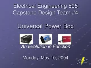
Electrical Engineering 595 Capstone Design Team #4 Universal Power Box
Staff • Gerry Callison, BSEE • Expertise: Power Systems, Digital Design, Presentation • Experience: 3 years experience at Johnsons Controls • Maria Schlicht, BSEE • Expertise: Micro controllers, PLCs, Project Management, Technical Writing, Language Skills • Experience: 8 years experience at Rockwell Automation • Ethan Spafford, BSEE • Expertise: RF, Circuit Design, Optical Communication, PSpice Software
Staff • Matt Risic, BSEE/BSCS • Expertise: High Level Programming, Assembly, Computer Networks, Computer Organization • Experience: Two summers interning at Philips Advance Transformer • Vanessa White, BSEE • Expertise: Digital Design, Micro controllers, PLC Logic • Experience: One year experience at Harley Davidson
Contact Info • Gerry Callison • Maria Schlicht • Ethan Spafford • Matt Risic • Vanessa White • Phone: (414) 510-1218 Email: gerrycallison@yahoo.com • Phone: (414) 382-1208 Email: maschlicht@ra.rockwell.com • Phone: (262) 332-0646 Email: espaff_@yahoo.com • Phone: (262) 893-3015 Email: mrisic@hotmail.com • Phone: (608) 212-7431 Email: vjwhite@uwm.edu
Weekly Availability Worksheet • Gerry Callison • Maria Schlicht • Ethan Spafford • Matt Risic • Vanessa White • Time 1: Monday nights Time 2: Friday any Time 3: Saturday any • Time 1: Monday after 5p Time 2: Tue after 4p Time 3: Fridays after 4p • Time 1: Monday after 5p Time 2: Tue after 4p Time 3: Fridays any Time 4: Sat any • Time 1: Monday after 7 Time 2: Tues any Time 3: Thursday 1-6 • Time 1: Monday after 5:30 Time 2: Fri after 5 Time 3: Saturday any Time 4: Sunday any
Weekly Project Meeting Plan • Weekly Meeting 1: 3rd Floor Lab, Monday 5-7 PM Owner: Gerry Callison • Weekly Meeting 2: 3rd Floor Lab, Tues 12-2 PM Owner: Matt Risic • Weekly Meeting 3: 3rd Floor Lab, Friday 12-2 PM Owner: Ethan Spafford • Weekly Meeting 4: 3rd Floor Lab, Sat 12-2 PM Owner: Maria Schlicht
Total Resources Estimate • 400 Manhours, approximately 80 per member • $300 or key part availability for material and prototyping
Information Media Roles • Website URL and Web master: Matt Risic • Project Archiver: Vanesssa White • Presentation Mgr: Gerry Callison • Report Mgrs: Maria Schlicht/Ethan Spafford
Project Selection • Best fit for scope of project and component availability • Fullest use of skills and experience of team • Major risks • Electrical Safety • Electronic Overload • Physical Durability • Other projects rejected for lack of variety in tasks and their limited scope • Decision unanimously supported by team • Selection Process • Majority vote after input from faculty advisors
Timeline February March April May Define Initial Design Component Selection Build Prototype Verification Refine Design Documentation
Time Line Summary Man Completion Hours Date • Basic Product Definition • Compilation/Definition of 2 2/4 Team Logistics/Operation • Team Resources Allocation 1 2/15 • Product Level Requirements 2 2/4 Standard/Performance • Proto-Type Block Diagram • Block Diagram with 2 2/5 Assignments and Interfaces • Block Review Team T/A 1 2/18 • Productization • Develop Product Level 3 4/10 Verification and Requirement Plan • Compilation/Development of MFG 4.5 4/30 Processes, Block Diagrams • Design Plans for Testing Disposal 4 4/19 and Service
Time Line Summary Est.Man Completion Hours Date • Proto-Typing • Integrate BL Proto-Type into 2 4/24 Product Level Proto-type • Testing of Fully Integrated 5 4/24 Proto-type • Execution of PL Verification/Validation 2 4/30 Plan • Compilation of Resource Expenditure 1 5/5 and Budget Chart • Documentation • Compilation of Individual 12.5 5/5 MSWord Reports • Compilation of Final MSWord Report 1 5/10 and PowerPoint Slide Show
Product Definition: User Requirements • Product: Universal Power Box • Industry Family: Consumer Electronics • Useful to eliminate the multitude of power adapters needed for many electronic devices so that they may be powered by any battery or standard wall plug regardless of the type of power required by the device • Intended for use in home electronics devices • The UPB will deliver power with simplicity! • Many different power adapters available, but none known that combine AC-DC, DC-AC, and DC-DC in one product
Refined Block Diagram Gerry Matt Maria Ethan Vanessa
3 MODES OF OPERATION • AC to DC. • DC to DC. • DC to AC.
AC to DC operation overview • AC voltage applied to I/O AC. • Uncontrolled Inverter/Rectifier converts AC to DC. • Buck-Boost converter adjusts output DC voltage to user-defined level.
DC to DC operation overview • User inputs DC to I/O DC. • Buck-boost converter adjusts DC to user defined level of DC. • Inverter/Rectifier switches configure to pass through output DC without altering it.
DC to AC operation overview • User inputs DC through I/O DC. • Buck-boost converter adjusts level of DC necessary for proper AC output. • Inverter/Rectifier runs PWM switching to output AC.
TOP-LEVEL FUNCTIONALITY REQUIREMENTS • The user can input 0-50Vdc or 0-120VAC to get out 0-50Vdc or 0-120VAC. • Separate adapter cables will allow for various power supplies to be connected to the UPB • The UPB will sense the level/type of input power, then output a user-defined level/type of power. • The UPB will be able to output 150 Watts of power. • The UPB will be able to output 5 Amps of current.
Power Control Matt Risic
Power Control Gerry Matt Maria Ethan Vanessa
Block Purpose • The Power Control is the center of the Universal Power Box • The programming is responsible for converting input waves into necessary output voltage waves. • This will vary from mode of operation.
ATMega88 Microprocessor • Uses RISC Architecture • 131 Instruction Set • C and Assembly Coding • 32 x 8 General Purpose Registers • 8KB Programmable Flash • 512 Bytes EEPROM • 1KB SRAM • 28 Pin Chip
ATMega88 Operating Conditions • Operating voltage between 1.8-5.5V • Operating temperature between -40 to +85 degrees Celsius • 0-6 MHz @ 1.8-5.5V, 0-12MHz @ 2.7-5.5V • At 1MHz consumes 1.8V, 240uA • At 32 kHz consumes 1.8V, 15uA • Power-down Mode is 0.1uA at 1.8V
Microprocessor Selection • Selected over other considerations because of best benefits per cost ratio. • Available locally or over Internet • Dependable and respectable manufacturer. • Manuals, examples and tutorials readily available.
AVR Studio 4 • Integrated Coding, Compiling and Debugging Software • Configurable Memory • Support for C, Pascal, BASIC and Assembly • Simulator Port Activity Logging and Pin Input
Standard RequirementsPower Control • Humidity Range 0%RH to 70%RH • Block Cost <$20 • Parts Count <30 • Block Size <48cm2 • Block Mass <95.5 grams • Max Power Consumption <20W • Operating Temperature Range 5C to 35C • Storage Temperature Range 0C to 50C • Operating Humidity 0-70% • Reliability (MTBF) 3 Years
Performance RequirementsPower Control • Input Voltage +3.3V (+/- 3%) • Full Scale Output Voltage +5V (+/- 3%) • Interfaces with User Interface, Control Power, Switch Driver, AC Sensor and Internal Sensor
Inverter-Rectifier Gerry Callison
Inverter-Rectifier Gerry Matt Maria Ethan Vanessa
Inverter/Rectifier functionality • H-bridge topology- allows for one circuit to function as inverter or rectifier. • H-bridge topology features four power-electronic switches. • IRF740A- MOSFET, 400V, 10A, Vgth=2-4V • Inverter- 2 phase pulse width modulated. • Rectifier- full wave, uncontrolled (meaning voltage level is not adjusted in this converter).
Inverter/Rectifier Interfaces • From Power Control: 0/3.3Vdc binary wave to drive PWM function. • MOSFET can be driven directly from Power Control (no driver needed). • To/from internal sensor: varying level of DC, depends upon user command. • To/from filter: varying power, depending on functionality.
Standard RequirementsInverter-Rectifier • Humidity Range 0 to 70 %RH • Block Cost <$6.00 • Parts Count <30 • Block Size <20cm2 • Block Mass <100grams • Max Power Consumption <3W • Operating Temperature Range 0C to 50C • Storage Temperature Range 0C to 50C • Operating Humidity 0-70%RH • Reliability (MTBF) 5 Years • Allocations • Cost 15% • Parts 15% • Unique Parts 14% • Power Cons. 20% • Mass 5% • Area PCB 12%
Performance RequirementsInverter-Rectifier • Input Voltage 0-50Vdc, 0-120VAC • Full Scale Output Voltage 0-50Vdc, 0-120VAC • Inverter/Rectifier Life 5 Years • % Error <10%
DC to DC Converter Gerry Callison
DC to DC Converter Gerry Matt Maria Ethan Vanessa
DC to DC functionality • Unique Challenge: Because of multidirectional flow of power, both ends needed to function as inputs or outputs. • Solution:Dual Buck-Boost converters, which share some parts. • A buck-boost converter can raise or lower DC voltage. • Requires 2 IRF740A MOSFETS. • This converter is where the voltage is adjusted to user-commanded level.
DC to DC interfaces • From Power Control: 0-3.3Vdc binary signal drives MOSFETs, manipulating output based upon duty cycle of signal. • MOSFETs driven directly from power control. • To/from DC sensor: Varying power, depending upon functionality. • To/from internal sensor: Varying level of DC, depending upon user command.
Standard RequirementsDC to DC Converter • Humidity Range 0 to 70 %RH • Block Cost <$4.00 • Parts Count <20 • Block Size <20cm2 • Block Mass <60grams • Max Power Consumption <3W • Operating Temperature Range 0C to 50C • Storage Temperature Range 0C to 50C • Operating Humidity 0-70%RH • Reliability (MTBF) 5 Years • Allocations • Cost 10% • Parts 10% • Unique Parts 5% • Power Cons. 20% • Mass 3% • Area PCB 7%
Performance RequirementsDC/DC Converter • Input Voltage 0-50Vdc, 0-120VAC • Full Scale Output Voltage 0-50Vdc, 0-120VAC • Inverter/Rectifier Life 5 Years • % Error <10%
User Interface Maria Schlicht
User Interface Gerry Matt Maria Ethan Vanessa
User Interface Overview • The User can select three modes of operation (AC–DC,DC-AC & DC-DC) • User can defined level/Type of power • The User can access to review or modify terminal settings by using the up and down arrows keys, navigate through the configuration screen. • Electrical Safety for User
User Interface Importance • Changing settings take affect immediately (without powering off the terminal) • User can reset the user interface without having to remove and then re-apply power or battery. • User friendly
Standard RequirementsUser Interface • Humidity Range 0%RH to 70%RH • Block Cost $10.00 • Parts Count 4 • Block Size 133 (H) x 111(W)x 48(D) mm • Block Mass 284 grams • Max Power Consumption 2.5 W max. (0.105 A @24Vdc) • Operating Temperature Range 0˚ C to 55˚C • Storage Temperature Range -20˚C to 85˚C • Operating Humidity 5 to 95% at 0˚ to 55˚C • Heat Dissipation 2.5W (8.5 BTU/Hour) • Reliability (MTBF) 5 Years • Allocations • Cost 25 % • Parts 5 % • Unique Parts 5 % • Power Cons. 5 % • Mass 5 % • Area PCB 5 %
Performance RequirementsUser Interface • Input Voltage +24V (+/-5%) • Full Scale Output Voltage +24V (+/-12%) • User Interface Life 5 Years • % Error 10% • Display (type) Liquid Crystal Display (LCD) with LED Backlighting • Display (size) 73mm (w) x 42mm (h) • Certifications UL CE marked for all applicable CSA (c-UL Class I Div 2 Hazardous)
AC Filter Ethan Spafford
AC Filter Gerry Matt Maria Ethan Vanessa