Download
1 / 11
110 likes | 216 Views
Resource assessment: uncertainty on system evaluation throughout life. Are all PR created equal ? . Irradiance Obstructers. Array Utilization. Unshaded Irradiance Incident on POA & Irradiance Obstructers. Module Conversion Efficiency. Losses in DC System. DC to DC. DC to AC.

E N D
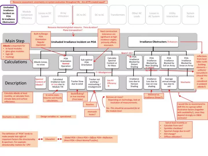
Resource assessment: uncertainty on system evaluation throughout life. Are all PR created equal? • Irradiance Obstructers Array Utilization Unshaded Irradiance Incident on POA & Irradiance Obstructers Module Conversion Efficiency Losses in DC System DC to DC DC to AC Transformers Other AC Loads Losses in AC System Utility Interaction System Output • Description • Main Step • Calculations • Unshaded Irradiance Incident on POA Resource Horizontal global resource. Time duration? Plane transposition? fixed construction tolerances are significant at high incidence angles; primarily affects mismatch. Built-in/DesignPOAOrientationRegularOperation • Sub-optimal POA Orientation • Irradiance Loss due to Horizon Shading • Average annual energy loss due to soil • POA Orientation Normal Operation • POA Irradiance Blocked by Snow on Array • Irradiance Loss due to row-on-row shading • POA Irradiance Blocked by Soil on Array • Calculate Spectral Content or Air Mass • POA Irradiance Blocked by Distant Shading • POA Irradiance Blocked by Near Shading • Albedo (snow, no snow /Enhancers • Albedo is important for • bi-facial modules • glass-glass modules • high-tilt • tracking) • Tracker Stow due to wind Beam? CC? reflections from local taller north building elements – uniform/nonuniform(should this be considered in ambient albedo?). • Tracker not working / mistracking / misalignment • Calculated Irradiance Gain or Loss due to Module Tilt or addedby reflection --?--Misalignment Spectral Content of Albedo? See PV Efficiency Stochastic Calculate albedo at least monthly, or calculate from climate data and surface reflectance. Backtracking? or true tracking (First Solar) Electrical vs. irradiance (linear?). In some cases, requires sub-hourly calculations. Remove air mass? Depending on technology, look at resolution of measurements. Yes. This should be accounted for at the module level. Baseline I would like to recommend to shift this to a group called illustrative factors (together with availability!), since they depend strongly on O&M contracts! mismatch losses? Stochastic vs. deterministic Design variables vs. operational. • Soil at least monthly or • Calculate from rain? • Sprinkler checkbox? • Spectral change due to soil? • AOI change? • Diffuse utilization?. The definition of “POA” tends to make people lose sight of important factors like directionality & spectrum. For example: directionality matters for CPV Global POA = Direct POA + Diffuse POA + Reflection. Direct POA = Direct Normal*cos(inc). Education
Module Conversion Efficiency Unshaded Irradiance Incident on POA & Irradiance Obstructers Module Conversion Efficiency Losses in DC System Array Utilization DC to DC DC to AC Transformers Other AC Loads Losses in AC System Utility Interaction System Output • Description • Calculations • Main Step • Spectral/air mass correction • Arb. Parametric ? • Don’t use air mass, use instead: • ‘useful fraction’, • ’APE’, • or ‘Blue fraction’ = Blue/(Blue+Red). • Clear sky spectrum varies with solar height. • Diffuse sky spectrum is an almost constant spectrum, bluer than AM 1.5. • IAM Factor on Global • Calculate Cell Temperature • Energy Loss due to operation other than at STC • Incident Angle Correction • Module Efficiency vs. Temperature • Module Rating Correction • Module Degradation • Module Efficiency vs. Irradiance • Light-Induced Degradation • Seasonal Annealing • Spectral/Air Mass Correction • What is module conversion efficiency based on? • STC • low radiation • other conditions? Which? • Ambient resource? • Incident angle correction • 1-D definition for flat plate only • IAMneeds to have the same symmetries as the receptor. • AR coating impact? • IEC61853-2 – Draft • Calculate cell temperature • Need non-steady state standardized parameters and models. • Tcell = Tamb + ΔT(δ)? • or capacity model • Dependence on efficiency & operating point. • Module temperature as a function of wind speed = temperature differences for edge modules. • NMOT ← (NOCT) • function of Tamb, GPOA, WS (0 – 7 m/s). • Module temperature as a function of wind speed = temperature differences for edge modules. • Mounting distance from roof, prevailing winds, etc. • IEC 61853-2 – Draft • Module efficiency vs. temperature: • Temperature coefficients at multiple irradiance levels are important for thin film. • Also alpha, beta, gamma. • IEC61853-1 & IEC61853-2 – Draft • Seasonal Annealing • Purely on month of year, or • on module temperature integrated over time. • Also a factor of total kWhrs for some thin-film technologies. • Module rating correction • Binning ← right distributions • Tolerance? Marketing Wp • Allowance for degradation. • For module efficiency vs. Irradiance • Irradiance can be plural • Irradiance components to be defined: • LCPVresponds differently to : • beam, CC, dome, horizon irradiance • diffuse, direct • Sandia faparameter (f1?) • Rshuntvs. G • Rseriesvs. G. • Light-induced degradation • Model stochastically. • Gaussian distribution μ, σ • Chart of ‘Time to Sta’ on y-axis (exp decay) • time varies with technology, .e.gaSI (3 months), cSI (day) • IEC 61215 – at least 20 kWhrs for c-Si technology. • Module degradation • Model stochastically. Gamma or lognormal distribution. • What degrades? • Rshuntdecreases, FF decreases, Rseries increases • will affect low light, high light performance. • PID? - or is this covered in this inherently? • Module degradation creates • system degradation. • OFF MPP OPERATION • = MPPT ‘Efficiency’ • lower inverter voltage limit • low power limit • high power limit • utility-commanded curtailment • could be a function of ‘smart’ junction boxes with microinverters Bin for atmospheric effects that we are not accounting for? 2 Multijunction: know whether top or bottom limited; worst junction limits with spectral change
Unshaded Irradiance Incident on POA & Irradiance Obstructers Module Conversion Efficiency Losses in DC System Array Utilization DC to DC DC to AC Transformers Other AC Loads Losses in AC System Utility Interaction System Output Fuse ohmiclosses are negligible. . Fuse availability losses: ‘DC health’. Diode forward drop can be noticeable. Diode/connector availability • Bypass diodes are part of IV-curves; • String diodes are not part of IV-curves => calculation • Negative voltage range? • Add string blocking diode (like PVSYST). • DC wiring losses • typically defined at STC and translated to other conditions; • if so, NOT a derate but an input to derate calculation • boost/buck converter will change this calculation. • Ioperational= Power/operational voltage • Wiring losses: aerial vs. buried? • This drives T, R(T) 3
Unshaded Irradiance Incident on POA & Irradiance Obstructers Module Conversion Efficiency Losses in DC System Array Utilization DC to DC DC to AC Transformers Other AC Loads Losses in AC System Utility Interaction System Output • Description • Calculations • Main Step • Array Utilization • Not at Array MPP • Current Mismatch in String • & Voltage Mismatch in Array ΣMod DC Out ΣMod MPP • Energy loss due to clipping due to high inverter temperature Energy loss due to temperature gradient Energy loss due to partial shading • Energy Loss due to module manufacturing variability • Energy loss due to imperfect MPP • Energy loss due to clipping due to inverter capacity limit Is this defines as f(T)? Is this DC or AC rating? • Energy loss due to clipping due to utility constraints Should this be a ‘loss’? Design vs. operational ● ● Increases with clipping Degradation/failures Partial shading of modules Crystalline vs. thin-film EN 50_ _ _European InverterEfficiency Standard. EN 50_ _ _European InverterData Sheet Standard. • Need Transparency of inputs and assumptions • – i.e. measurable quantities • – Isc0/Imp from a sample set vs. the effect of measurable quantities. • Module --> module mismatch = X% derate factor • NOT the same Static & dynamic tracking efficiency Hourly simulation? • UNEVEN SOIL OR SNOW • Even soiling = derate factor • Uneven soiling = mismatch --> calculations --> derate) • What is AC conversion efficiency? • OR If you have per-module measurements then the array utilization concerns lead to loss in the modules before wiring losses. Voltage Drop Across Array Environmental Bucket? Measurable voltage mismatch vs. energy lost due to that 4
Unshaded Irradiance Incident on POA & Irradiance Obstructers Module Conversion Efficiency Losses in DC System Array Utilization DC to DC DC to AC Transformers Other AC Loads Losses in AC System Utility Interaction System Output (Shared in DC to AC) Converter: Off – MPPT. Differs based on principals of operation. Affects inverter efficiency. Buck only: (DC-DC) + Inverter clipping = Converter bypass, leading to mismatch in modules. Buck-Boost: (DC-DC) + Inverter Clipping = Converter Efficiency Hit • Multiple units per inverter; • May be not uniformly allocatedM • may have multiple OP nodes;: • Bypass • Convert. Need Standard for DC to DC efficiency outside of inverter (Second)Voltage buck/boost ratio+Power 5
Unshaded Irradiance Incident on POA & Irradiance Obstructers Module Conversion Efficiency Losses in DC System Array Utilization DC to DC DC to AC Transformers Other AC Loads Losses in AC System Utility Interaction System Output (Shared in DC to DC) Better Characterization by inverter manufacturers; function of voltage, temperature, light. Actual Operational Voltage Range vs. MPPT Voltage Range • Poutis proportional to Iout with constant Vout. Imperfect MPPT tracking – here or mismatch? → How do you quantify this? → Neither – Mismatch moves MP, off MP is different. Is the ‘Inverter Efficiency Adjustment’ to capture the derating of the inverter due to high temperatures/elevation adjustments? There are losses due to the array falling out of the operating parameters of the inverter: low/high voltage, low power... Inverter adjustment is not well defined. Power Block definition as AC output at inverter could be useful. Power measurement point (analogous to power curve for wind machine). Challenge: can power output curve be represented vs. POA incident irradiance (e.g. 200, 400, 600, 800) at a single standard NOCT – then adjust for actual/modeled POA and NOCT? 6
Unshaded Irradiance Incident on POA & Irradiance Obstructers Module Conversion Efficiency Losses in DC System Array Utilization DC to DC DC to AC Transformers Other AC Loads Losses in AC System Utility Interaction System Output Why only daytime losses? Are constant losses captures somewhere else? Only if nighttime switch is present (very unusual!) Dynamic/static Cooling fans? 7
Unshaded Irradiance Incident on POA & Irradiance Obstructers Module Conversion Efficiency Losses in DC System Array Utilization DC to DC DC to AC Transformers Other AC Loads Losses in AC System Utility Interaction System Output Heater loads could be time-of-day or seasonal,and can be a large percentage at low irradiance levels and low temperatures, e.g. Ontario winter. Auxiliary loads are sometimes subtracted from the delivered energy, sometimes not! (FIT,...) Right, need to know how the metering is configured. 8
Unshaded Irradiance Incident on POA & Irradiance Obstructers Module Conversion Efficiency Losses in DC System Array Utilization DC to DC DC to AC Transformers Other AC Loads Losses in AC System Utility Interaction System Output • Ohmic • For large plants, reactive current loss becomes noticeable. • In General: • descriptions more extensive examples. • Don’t use a factor if it is a complex calculation; or, if necessary, add this information • . 9
Unshaded Irradiance Incident on POA & Irradiance Obstructers Module Conversion Efficiency Losses in DC System Array Utilization DC to DC DC to AC Transformers Other AC Loads Losses in AC System Utility Interaction System Output Q Higher Current ? Grid Branch Only? P PV Description Necessary ! VAR Requirements May affect yield PF, Plant controllers: how do these interact with current tools? 10
Unshaded Irradiance Incident on POA & Irradiance Obstructers Module Conversion Efficiency Losses in DC System Array Utilization DC to DC DC to AC Transformers Other AC Loads Losses in AC System Utility Interaction System Output Should be based on component distributions, → feeds all other factors (losses should be captured elsewhere). Break out the losses that occur during downtime Coming from what? Does it need to be broken out? Ohmic,…) Alternative Modes of operation Availability ultimately energy (% loss) but starts as time loss. What are we putting in system degradation? Everything but modules? Are there other industries we can draw from for ideas; wind? • New step after ‘System Output’ • Night-time Consumption --> ‘Brown Power’ • Transformers • Inverters • SCADA • heating/cooling/other How do we measure availability? = resource assessment pre unshadedirradiance on POA. 11