Download
1 / 16
160 likes | 257 Views
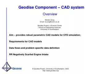
Engineering Group 402-150 Eglinton Ave. E., Toronto ON M4P 1E8 * Phone: (416) 544-8160. Inventor CAD System Integration. Michael Trauttmansdorff michael@trauttmansdorff.ca 416 528 1253. Introduction and Outline. Model of the Wildfire Spacecraft Overview of CAD using Inventor

E N D
Engineering Group 402-150 Eglinton Ave. E., Toronto ON M4P 1E8 * Phone: (416) 544-8160 Inventor CAD System Integration Michael Trauttmansdorff michael@trauttmansdorff.ca 416 528 1253
Introduction and Outline • Model of the Wildfire Spacecraft • Overview of CAD using Inventor • Parametric Modeling • Advanced Parameter Control • Optimization Process • Closing the design loop
1. Model of the Wildfire Spacecraft The CAD Model serves several purposes: • Visualization • Determine mass & moments of inertia • Geometry for FEA Analysis • Final Production Drawings
1. Model of the Wildfire Spacecraft Engine Aeroshell Fuel Tank Capsule Rendering of the model in AutoDesk Inventor 7
2. Overview of CAD using Inventor Inventor is a fully parametric modeling environment This means that part dimensions can be linked, and made interdependant
2. Overview of CAD using Inventor Parameterization In Action This Dimension sets the height of the truss Truss in rocket block connecting the solid motor to the primary fuel tank
2. Overview of CAD using Inventor Parameterization In Action Changing this dimension modifies the entire truss. Truss in rocket block connecting the solid motor to the primary fuel tank
2. Overview of CAD using Inventor Advanced Parameters Control: • AutoDesk Inventor can link all of its parameters to a spreadsheet • Using excel, a parameter control sheet is created which contains all the dimensions which affect the model • This sheet, instead of part specific dialog boxes, is where modifications to dimensions are made
2. Overview of CAD using Inventor Subsystem Analysis And Calculation Sheet Capsule Subsystem Parameter Sheet Subsystem Analysis And Calculation Sheet Capsule Design Overview Capsule Subsystem Parameter Sheet Subsystem Analysis And Calculation Sheet Capsule Subsystem Parameter Sheet CAD Model Overall Design Subsystem Analysis And Calculation Sheet RB Subsystem Parameter Sheet Subsystem Analysis And Calculation Sheet RB Design Overview RB Subsystem Parameter Sheet Subsystem Analysis And Calculation Sheet RB Subsystem Parameter Sheet Concept Implementation Product
3. Optimization Process • Design optimization is achieved by iteration • Results from one level of analysis are used to refine the next level.
3. Optimization Process Main tools in the design process • Matlab Simulation • Inventor CAD • Ansys FEA Analysis Integration is achieved by linking the outputs and inputs of these tools using spreadsheets
3. Optimization Process Information Flow in Computer Aided Design Mission Simulation Analysis Model Fully Integrated Design Drawings Rocket
3. Optimization Process Closing the Design Loop • The Forward flow of design parameters ensures consistency • Adding feedback allows the design to converge to an optimal point
3. Optimization Process • Current level of Integration : • Feedback between the Simulation and CAD Model • Direct use of CAD Model in FEA using Ansys Design Space • Target Level: • Full Integration
3. Optimization Process Information Flow in Computer Aided Design Mission Simulation Analysis - - Model Feedback Integrated Design Drawings Rocket