Download
1 / 14
140 likes | 232 Views
Use of a novel Controlled Drift Detector for Diffraction Enhanced Breast Imaging. S. Pani, G. Royle, R. Speller – University College London, Department of Medical Physics and Bioengineering A. Castoldi, A. Galimberti, C. Guazzoni – Politecnico di Milano and INFN, Sezione di Milano. Outline.

E N D
Use of a novel Controlled Drift Detector for Diffraction Enhanced Breast Imaging S. Pani, G. Royle, R. Speller – University College London, Department of Medical Physics and Bioengineering A. Castoldi, A. Galimberti, C. Guazzoni – Politecnico di Milano and INFN, Sezione di Milano
Outline • Principles and constraints of Diffraction Enhanced Breast Imaging (DEBI) • The Controlled Drift Detector (CDD) • Results with monochromatic radiation • Future applications
Conventional Breast Imaging PC Johns and MJ Yaffe, Phys Med Biol 1987 • The main limitation of conventional mammography is the small difference between the attenuation coefficients of fibroglandular tissue and carcinoma fibrous IDC
G. Kidane et al., Phys Med Biol 1999 c=1.7 nm-1 c=1.1 nm-1 c=1/l sin (q/2) Diffraction Enhanced Breast Imaging (DEBI) • DEBI is based on the detection of the diffraction pattern produced by coherently scattered X-rays • The diffraction pattern of normal and neoplastic breast tissue are significantly different
Polychromatic beam Scattered photons at a given angle are detected with a HPGe detector Can be used with a conventional source Several values of the momentum transfer can be investigated simultaneously Non position sensitive incoming beam collimator HPGe E1 E2 c2 c1 Energy-dispersive DEBI
low-noise CCD multi-hole collimator monochromatic beam diffracted beam Synchrotron radiation DEBI • Monochromatic radiation • Different values of the momentum transfer are achieved by changing either E or q • Position sensitive technique • Difficult implementation on conventional sources
The “ideal” detector for DEBI • Low noise (single-photon counting) • Position sensitive • Spectroscopic capability
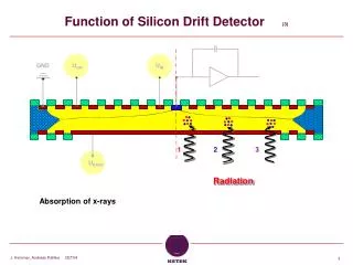
A Castoldi et al., IEEE TNS 1997 integration phase readout phase The Controlled Drift DetectorPolitecnico/INFN Milano, MPI Munich • Combines the pixel structure of a CCD with the fast readout typical of a SDD • Integration time ~ 1-6 µs • High frame rate • Low thermal noise • Prototype characteristics: • 3.96 x 6.12 mm2, • pixel size180 µm2 • Thickness 300 µm • Edrift: 400 V/cm Frame rate: 50 kHz • Energy resolution: • 2.15 keV FWHM @18 keV, room temperature (high leakage current)
CDD + collimator phantom y translation monochromatic X-ray beam goniometer + vertical adjustment x translation stage Experimental set-up at ELETTRA • Goniometer at 9 degrees for diffraction images • Beam energy 18 keV (c=1.1 nm-1) and 26 keV (c=1.7 nm-1) • Multi-hole collimator (500 µm hole - 500 µm spacing) • Both transmission and diffraction images
pile-up 3rd harmonic 4th harmonic Tr – plexi1 18 keV Diff – plexi1 18 keV Tr – plexi2 18 keV Diff – plexi2 18 keV Diff – plexi2 26 keV CDD spectra • Images were obtained by integrating • The counts within a 5 keV window • The full spectrum
CONTRAST Full spect (%) CONTRAST 5 keV (%) Transmission 18 keV 29±2 28±2 Diffraction 18 keV 48±3 49±4 Transmission 26 keV 12±1 11±1 Diffraction 26 keV 30±3 30±2 Meat sample 1 Thickness ~ 5 mm
CONTRAST Full spect (%) CONTRAST 5 keV(%) Transmission 18 keV 33±3 34±3 Diffraction 18 keV 46±5 44±4 Transmission 26 keV 11±1 10±1 Diffraction 26 keV 29±2 27±2 Meat sample 2 Thickness ~ 5 mm
Conclusions and perspectives • The performance of the CDD in its application to DEBI was tested with a monochromatic source • No significant difference was observed between full-spectrum/photopeak integration, BUT • In the future: use of the CDD for DEBI with conventional sources • Energy dispersive, position-sensitive DEBI
Acknowledgment S. Pani was supported by a Marie-Curie Intra-European Fellowship (MEIF-CT-2004-007206) within the 6th European Community Framework Programme