Download
1 / 24
450 likes | 1.94k Views
Tape-Spring Rolling Hinges. Alan M. Watt. Outline of Talk. Why build new hinges. What is a tape-spring rolling hinge. Previous designs. Conceptual design. Stiffness of hinge. Moment - rotation properties. Damping. Wire Effects. Applications of hinges. Why build new hinges.

E N D
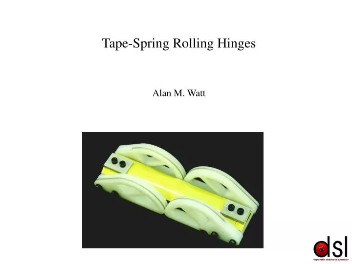
Tape-Spring Rolling Hinges Alan M. Watt
Outline of Talk • Why build new hinges. • What is a tape-spring rolling hinge. • Previous designs. • Conceptual design. • Stiffness of hinge. • Moment - rotation properties. • Damping. • Wire Effects. • Applications of hinges.
Why build new hinges Present designs rely on motors or complex hinge assemblies to drive mechanisms. • Complex. • Require power. • Heavy. • Stiff (large, heavy) support frames required. • Unreliable
What is a Tape-Spring Rolling Hinge • Benefits of tape-springs: • Deployment moment. • Locking moment. • Very light weight and simple. • Good pointing accuracy. • Problem: • - No constraint when undeployed. Benefits of rolling hinges: • Very low friction (rolling contact only). • No lubrication required. • Constrained deployment. Two arrangements of tape-springs.
Aerospatiale “Adele” Hinge • Very complex. • Wide. • Locking mechanism required. • Complex band tightening mechanism. • Heavy – 1.1 kG
Astro / JPL Nasa Hinge • Simpler than Aerospatiale hinge. • Tightening mechanism simpler. • Still very wide. • Small locking moment, as tape-springs almost co-planar.
Hinge Design Parameters R=radius of curvature of tape-spring • S – spacing • d – offset Assuming standard tape-springs, there are four variable parameters: • r – radius • L - Length Three main constraints: • S-d < r • d > s/2 • L > 2pR Can lead to hinge that operates in one direction only.
Solve for and substitute into Calculation of Mmax Considering Local buckling at point 2. Stress in eccentrically loaded strut = shell buckling stress. Comparison to FE Calculation
Deployed Stiffness of Hinge Deployed stiffness required for natural frequency analysis and dynamic simulations. • 3 linear stiffnesses: • Extensional, in-plane shear (Y), out of plane shear (Z). • 3 torsional stiffnesses: • Torsional, in-plane bending (about Z), out of plane bending (about Y). • Each can be found for tape or rolling hinge on their own as well as the combination. Generally require high deployed stiffness and low stowed stiffness.
Extensional Stiffness of Tape-Spring • Dead band caused by play in test set-up – now fixed although no results. • Predictions made using FE and beam models. Poor correlation between prediction and experiment. 10 kN/mm to 3 kN/mm respectively.
Extensional Stiffness of Rolling Hinge Stiffness predicted using FE model made in Pro/Mechanica with 2940 tetra elements and contact surface at join of hinge. Analysis is only true as long as wires are kept under sufficient tension to maintain compressive contact. Stiffness results compare reasonably with practical results 1530 N/mm – 1040 N/mm.
with Extensional Stiffness of Rolling Hinge (cntd) For faster analysis equivalent bar model using hertzian contact theory was developed. Hertz theory gives approach (d) of bodies as:
Shear Stiffnesses Out-of-Plane hinge stiffness Predictions found from finite element analysis and beam bending theory. Good match found for rolling hinge part of hinge but tape-spring results high. Stiffness predominantly arises from tape-spring for out-of-plane direction and rolling hinge for in-plane direction.
Torsional Stiffness Experimental measurements taken with FSH testing machine with rotating head. Experiments matched predictions reasonably well. Rolling hinge and tape both contribute to stiffness.
Bending Stiffnesses Predictions found from FE analysis and beam theory. Poor match between predictions and experimental results.
Moment - Rotation Properties • Manual data capture. • Hard to capture peak moment. • Results match FE model well. • Redesign of hinge based on data. • New automated set-up to be used to obtain peak moment and test hinges of different sizes.
Damping • Two types of Damping: • During deployment, to slow the hinge deployment time. • At locking, to lower shock transmitted to structure and prevent re-buckling of tape-springs. A number of damping schemes were considered. There are few that apply true damping without adding greatly to the complexity of the hinge. Constrained layer damping added to tape-springs. Aluminium layer with damping material underneath. Preliminary tests suggest that constrained layer damping is relatively ineffective and that there is a large amount of natural damping in the hinge at locking.
Analysis of Wire Effects For a given configuration, a straight section of wire tangentially links two points on either side of the hinge. From this the position of the wire can be found for any hinge configuration.
Analysis of Wire Effects (cntd) Moment - rotation can be found from a number of analytical methods: • Virtual Work–Mq=Fe • M=2F(L2-L1) • M=Rd
Tensioning Hinge A set-up such as this, with the wire transferring from a large radius to a small one provides a moment (due to tensioning of wires) proportional to rotation. Can be applied to current hinge design simply by cutting some of the grooves deeper than others, to increase the moment provided by the hinge. Moment is still proportional to rotation and work is ongoing to find layout to give near linear moment.
Dynamic Modelling • Model made for Pro/Mechanica simulation of deployments. • Hinge acts as two pin joints separated by a constant distance. • Joint angles forced to be equal or gear pair added.
Applications of New Hinges • Deployable solar panels with cold mirrors for QinetiQ (formerly DERA). • Deployable Synthetic Aperture Radar for QinetiQ. • Deployable Synthetic Aperture Radar for Astrium (formerly Matra Marconi Space). • Deployable Radiator for Astrium.