Download

1 / 47
500 likes | 583 Views
Explore the latest advancements in Left Ventricular Assist Device (LVAD) technology, including system goals, concept generation, materials, testing methods, and ergonomic considerations for enhanced patient experience.

E N D
System Overview SmihaSayal
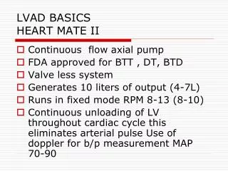
System Overview • Left Ventricular Assist Device (LVAD) • Mechanical device that helps pump blood from the heart to the rest of the body. • Implanted in patients with heart diseases or poor heart function.
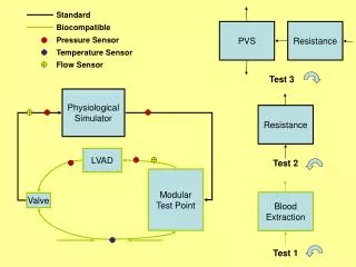
System Goal • Miniaturize the existing LVAD system to achieve portability while retaining its safety and reliability.
Original System • “Black box” architecture used during development • Large, not portable • Runs on AC power
P10021’s System • Has both internal / external components • Equivalent to our “Option 2” • Unfinished implementation
Customer Needs • Safe • Robust • Affordable • Easy to wear and use • Interactive with user • Controllable by skilled technician • Comparable performance • Compatible with existing pump
Other LVAD Technologies CorAide (NASA)
Concepts: Option 1 All electronics external
Concepts: Option 2 ADC internal only
Concepts: Option 3 Pump and motor control internal
Concepts: Option 4 All electronics and battery internal
Concept Generation Highlights Best Option 350 273 200 153
Enclosure Design Nicole Varble and Jason Walzer
Material and Processing Selection • Needs • The external package should be lightweight/ robust/ water resistant • The devices should be competitive with current devices • The device should fit into a small pouch and be comfortable for user • Specification • Based on the HeartMate II • Optimum weight of 4 lbs • Optimum volume of 56 in3 • Risks • Housing for the electronics is too heavy/large/uncomfortable • Preventative measures • Eliminate heavy weight materials • Eliminate weak, flexible materials • Material is ideally machinable
Water Resistant Testing • Need: The external package should resist minor splashing • Specification: Water Ingress Tests • Once model is constructed, (user interface, connectors sealed, lid in place) exclude internal electronics and perform test • Monitor flow rate (length of time and volume) of water • Asses the quality to which water is prevented from entering case • Risk: Water can enter the external package and harm the electronics • Preventative measures: • Spray on Rubber Coating or adhesive • O-rings around each screw well and around the lid • Loctite at connectors Spray on Rubberizd Coating Spray on Silicon Guard http://scoutparts.com/products/?view=product&product_id=14074 http://safetycentral.com/watspraysilw.html http://www.smooth-on.com/Spray-Materials-St/c1281_1287/index.html?catdepth=1 Urethane Plastic Spray-On Coat
Robustness Testing • Need: The device should survive a fall from the hip • Specification: Drop Test • Drop external housing 3-5 times from hip height, device should remain fully intact • Specify and build internal electrical components • Identify the “most venerable” electrical component(s) which may be susceptible to breaking upon a drop • Mimic those components using comparable (but inexpensive and replaceable) electrical components • Goal • Show the housing will not fail • Show electronics package will not fail, when subjected to multiple drop tests • Risks • The housing fails before the electronic components in drop tests • The electronic components can not survive multiple drop tests • Preventative Measures • Eliminate snap hinges from housing (screw wells to secure lid) • Test the housing first • Take careful consideration when developing a thickness of the geometry • Design a compact electronics package
Heat Dissipation to the Body • Need • Internal Enclosure must dissipate a safe amount of heat to the body • Risk • Internal electronics emit unsafe amounts of heat to body causing tissue necrosis • Benchmarking • Series of tests studied constant power density heat sources related to artificial hearts • 60-mW sources altered surface temperatures 4.5, 3.4, 1.8 °C above normal at 2, 4, 7 weeks • Internal devices must not increase surrounding tissue by more than 2°C • Specifications • 40mW/cm2 (source increased to upper limit of 1.8 °C) Wolf, Patrick D. "Thermal Considerations for the Design of an Implanted Cortical Brain–Machine Interface (BMI)." Ncib.gov. National Center for Biotechnology Information, 2008. Web. 30 Sept. 2010. <http://www.ncbi.nlm.nih.gov/bookshelf/br.fcgi?book=frimp∂=ch3>.
Ergonomics • Need: Device should be comfortable for user • ANSUR Database • Exhaustive military database outlining body dimensions • Waist Circumference (114) • Males: 137.3 mm • Females: 126.0 mm • Waist Depth (115) • Males: 113.1 mm • Females: 102 mm • Calculated average radius of hip • Males: 125.2 mm • Females: 114.0 mm • Acceptable Avg. Radius of hip • ~120 mm
Rapid Prototyping • Machinable • Material can be drilled (carefully) and tapped • Accepts CAD drawings • Obscure geometries can be created easily • Ideal for proposed ergonomic shape • Builds with support layer • Models can be built with working/moving hinges without having to worry about pins • Capable of building thin geometries • Stereolithography • UV curable polymer resin • Creates a non-porous solid • Enclosure will be waterproof and not require additional coating • Lightweight – Specific gravity of 1.17 • Dimension System • ABSplus • Industrial thermoplastic • Lightweight - Specific gravity of 1.04 • Porous • Does not address water resistant need http://www.dimensionprinting.com/
ABS Plastic • Important Notes • Relatively high tensile strength • Glass Transition well above body temperature • Specific Gravity indicates lightweight material
Enclosure Concept • CAD model is can be easily resized • Removable top panel for electronics access
Embedded Control System Andrew Hoag and Zack Shivers
Control System • Requirements • Selecting suitable embedded control system • Designing port of control logic to embedded system architecture • Customer Needs • Device is compatible with current LVAD • Device is portable/small • Allows debug access
Impeller Levitation • Impeller must be levitating or “floating” • Electromagnets control force exerted on impeller • Keeps impeller stabilized in the center • Position error measured by Hall Effect sensors
Levitation Algorithm • Algorithm complexity influences microcontroller choice • Electronics choices affect volume / weight • Proportional – Integral – Derivative (PID) • Very common, low complexity control scheme http://en.wikipedia.org/wiki/PID_controller
Embedded System Selection • Requirements: • Can handle PID calculations • Has at least 8x 12-bit ADC for sensors at 2000 samples/sec • Multiple PWM outputs to motor controller(s) • Same control logic as current LVAD system • Reprogrammable
Embedded System Selection • Custom Embedded • dsPIC Microcontroller • Blocks for Simulink • Small • Inexpensive (<$10 a piece) • TI MSP430 • Inexpensive (<$8 a piece) • Small, low power • COTS Embedded • National Instruments Embedded • Uses LabVIEW • Manufacturer of current test and data acquisition system in “Big Black Box” • Large to very large • Very expensive (>$2000)
Control Logic/Software • Closed-loop feedback control using PID – currently modeled in Simulink for use with the in “Big Black Box” • Additional microcontroller-specific software will be required to configure and use A/D, interrupts, timers.
Life Critical System • Not at subsystem level detail yet. • Life-critical operations would run on main microcontroller. • User-interface operations run on separate microcontroller. • Possible LRU (Least Replaceable Unit) scheme
Technician/Field Software Debug Interface • USB • USB is everywhere. • Requires custom PC-side software. • Requires processor support. • Serial (RS-232) • Many computers don’t have serial ports anymore. • Can use $15 COTS USB to Serial adapter. • Can use COTS terminal tools.
Technician/Field Software Debug Interface • Example of using COTS tool – Windows HyperTerminal (free/part of Windows)
Microcontroller Search Parameters • A/D • 0-5V • 8x12-bit @5ksps (kilo-samples/sec) • This equates to 40ksps minimum for A/D • PWM • General I/O for UI controls • At least 10x digital • At least 5x analog • UART (for Serial connection)
Microcontroller Packaging • L/TQFP – Low-profile/Thin Quad Flat Pack • Small surface-mount (PCB mount) chip package. • Is solderable (by skilled solderer) • Body thickness up to 1.0mm, sizes range from 5x5mm to 20x20mm
Microcontroller • 2 families of Microcontrollers • dsPIC from Microchip • MSP430 from Texas Instruments
Microchip dsPIC • dsPIC30F5011 (16-bit architecture) • Max CPU speed 30 MIPS (Million Instructions/sec) • 2.5-5.5V operating voltage • 66KB Flash, 4KB RAM, 1KB EEPROM • 16x12-bit ADC @ 200ksps • -40 to 85C operating temp • 64-lead TQFP – body 10x10mm, overall 12x12mm • Cost [1-25 units] = $7.21
TI MSP430 • MSP430F5435A (16-bit architecture) • Max CPU speed 25 MIPS (Million Instructions/sec) • 2.2-3.6V operating voltage • 192KB Flash, 16KB RAM • 16x12-bit ADC @ 200ksps • 3 Timer modules (with total of 15 timer channels) • -40 to 85C operating temp • 80-lead LQFP – body 10x10mm, overall 12x12mm
Next Steps Juan Jackson
Tasks • Battery analysis • Motor controller research and selection • Enclosure final design • Further microcontroller analysis • Embedded code • Cost analysis
Questions / Comments Help us improve our design!