Download
1 / 36
400 likes | 777 Views
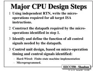
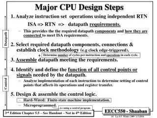
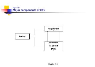
Figure 8-1 Major components of CPU. Register Set [. Control. Arithmetic Logic unit (ALU) [. Figure 8-2 Register set with common ALU. INPUT. 3 X 8 decoder. MUX. MUX. SELA. SELB. Arithmetic logic unit (ALU). OPR. output. Table 8-1 Encoding of Register Selection Fields.

E N D
Figure 8-1Major components of CPU Register Set [ Control Arithmetic Logic unit (ALU) [ Chapter # 8
Figure 8-2Register set with common ALU INPUT 3 X 8 decoder MUX MUX SELA SELB Arithmetic logic unit (ALU) OPR output Chapter # 8
Table 8-1Encoding of Register Selection Fields. Binary Code SELA SELB SELD 000 Input Input None 001 R1 R1 R1 010 R2 R2 R2 011 R3 R3 R3 100 R4 R4 R4 101 R5 R5 R5 110 R6 R6 R6 111 R7 R7 R7 Chapter # 8
Table 8-2Encoding of ALU operations. OPR Select Operation Symbol 00000 Transfer A TSFA 00001 Increment A INCA 00010 Add A + B ADD 00101 Subtract A – B SUB 00110 Decrement A DECA 01000 AND A and B AND 01010 OR A and B OR 01100 XOR A and B XOR 01110 Complement A COMA 10000 Shift right A SHRA 11000 Shift left A SHLA Chapter # 8
Binary Code for Subtract Micro operation. R1R2 – R3 Field: SELA SELB SELD OPR Symbol: R2 R3 R1 SUB Control Word 010 011 001 00001 Chapter # 8
Table 8-3Examples of Micro operations for the CPU. Symbolic Designation Micro operation SELA SELB SELD OPR Control Word R1 R2 – R3 R2 R3 R1 SUB 010 011 001 00101 R4 R4 R5 R4 R5 R4 OR 100 101 100 01010 R6 R6 + 1 R6 - R6 INCA 110 000 110 00001 R7 R1 R1 - R7 TSFA 001 000 111 00000 Output R2 R2 - None TSFA 010 000 000 00000 Output Input Input - None TSFA 000 000 000 00000 R4 shl R4 R4 - R4 SHLA 100 000 100 11000 R5 0 R5 R5 R5 XOR 101 101 101 01100 Chapter # 8
Figure 8-3Block Diagram of a 64-word stack. Address 63 FULL EMTY 4 C SP 3 2 B A 1 0 DR Chapter # 8
Push and Pop Micro operations Push SPSP + 1 Increment stack pointer M[SP] DR Write item on top of the stack If (SP = 0) then (FULL 1) Check if stack is full EMTY 0 Mark the stack not empty Pop DRM[SP] Read item from the top of stack SP SP – 1 Decrement stack pointer If (SP = 0) then (EMTY 1) Check if stack is empty FULL 0 Mark the stack not Full Chapter # 8
Figure 8-4Computer memory with program, data, and stack segments. Memory Unit 1000 PC 2000 AR 3000 3997 SP 3998 3999 4000 4001 DR Chapter # 8
Figure 8-5Stack operations to evaluate 3 . 4 + 5 . 6 6 5 4 5 30 3 12 42 12 3 12 12 . . + 3 4 5 6 Chapter # 8
The most common fields in instruction formats 1. An operation code field that specifies the operation to be performed. 2. An address field that designates a memory address or a processor register 3. A mode field that specifies the way the operand or the effective address is determined Three types of CPU organization 1. Single accumulator organization. 2. General register organization. 3. Stack organization. Chapter # 8
Three Address Instructions Expression: X= (A + B) * (C + D) Assembly language program. ADD R1, A, B R1 M[A] + M[B] ADD R2, C, D R2 M[C] + M[D] ADD X, R1, R2 M[X] R1 * R2 Chapter # 8
Two-Address Instructions Expression: X= (A + B) * (C + D) Assembly language program. MOV R1, A R1 M[A] ADD R1, B R1 R1 + M[B] MOV R2, C R2 M [C] ADD R2, D R2 R2 + M[D] MUL R1, R2 R1 R1 * R2 MOV X, R1 M[X] R1 Chapter # 8
One-Address Instructions Expression: X= (A + B) * (C + D) Assembly language program. LOAD A AC M[A] ADD B AC AC + M[B] STORE T M[T] AC LOAD C AC M[C] ADD D AC AC + M[D] MUL T AC AC * M[T] STORE X M[X] AC Chapter # 8
Zero-Address Instruction. Expression: X= (A + B) * (C + D) Assembly language program. PUSH A TOS A PUSH B TOS B ADD TOS (A + B ) PUSH C TOS C PUSH D TOS D ADD TOS (C + D) MUL TOS (A + B)*(C + D) POP X M[X] TOS NOTE: TOS stands for top of stack Chapter # 8
RISC Instructions Expression: X= (A + B) * (C + D) Assembly language program. LOAD R1, A R1 M[A] LOAD R2, B R2 M[B] LOAD R3, C R3 M[C] LOAD R4, D R4 M[D] ADD R1, R1 ,R2 R1 R1+R2 ADD R3, R3 ,R2 R3 R3+R4 MUL R1, R1, R3 R1 R1 * R3 STORE X,R1 M[X] R1 Chapter # 8
Addressing Modes • Implied Mode • Immediate Mode • Register Mode • Register Indirect Mode • Auto increment or Auto decrement Mode • Direct Address Mode • Indirect Address Mode • Relative Address Mode • Indexed Addressing Mode • Base Register Addressing Mode Chapter # 8
Figure 8-7Numerical example for addressing modes Address Memory 200 Load to AC Mode PC=200 201 Address = 500 202 Next instruction R1=400 XR= 100 AC 399 450 400 700 500 800 600 900 702 325 800 300 Chapter # 8
Table 8-4Tabular List of Numerical Example Addressing Mode Effective Address Content of AC Direct Address 500 800 Immediate operand 201 500 Indirect Address 800 300 Relative Address 702 325 Indexed Address 600 900 Register - 400 Register Indirect 400 700 Auto increment 400 700 Auto decrement 399 450 Chapter # 8
Table 8-5Typical Data Transfer Instructions. Name Mnemonic Load LD Store ST Move MOV Exchange XCH Input IN Output OUT Push PUSH Pop POP Chapter # 8
Table 8-6Eight Addressing Modes for the Load Instruction. Assembly Mode Convention Register Transfer Direct address LD ADR AC M[ADR] Indirect address LD @ADR AC M[M [ADR] ] Register relative LD $ADR AC M[PC + ADR] Immediate operand LD # NBR AC NBR Index addressing LD ADR(X) AC M[ADR + XR] Register LD R1 AC R1 Register indirect LD (R1) AC M[R1] Auto increment LD (R1)+ AC M[R1], R1 R1 + 1 Chapter # 8
Table 8-7Typical Arithmetic instructions Name Mnemonic Increment INC Decrement DEC Add ADD Subtract SUB Multiply MUL Divide DIV Add with carry ADDC Subtract with borrow SUBB Negate(2’s Comp ) NEG Chapter # 8
Table 8-8Typical Logical and Bit Manipulation Instructions. Name Mnemonic Clear CLR Complement COM AND AND OR OR Exclusive-OR XOR Clear carry CLRC Set carry SETC Complement carry COMC Enable interrupt EI Disable interrupt DI Chapter # 8
Table 8-9Typical Shift Instructions Name Mnemonic Logical shift right SHR Logical shift left SHL Arithmetic shift right SHRA Arithmetic shift left SHRL Rotate right ROR Rotate left ROL Rotate right through carry RORC Rotate left through carry ROLC Chapter # 8
Table 8-9Typical Program Control Instructions Name Mnemonic Branch BR Jump JMP Skip SKP Call CALL Return RET Compare (by subtraction) CMP Test (by ANDing) TST Chapter # 8
Shift Bit Conditions. • Bit C (carry) is set to 1 if the end carry C8 is 1. It is cleared to 0 if the carry is 0. • Bit S (sign) is set to 1 if the highest-order bit F7 is 1. It is set to 0 if the bit is 0. • Bit Z (zero) is set to 1 if the output of ALU contains all 0’s. It is cleared to 0 otherwise. In other words, Z=1 if the out put is zero and Z=0 if the output is not zero. • Bit V (overflow) is set to 1 if the exclusive-OR of the last two carries is equal to 1, and cleared to 0 otherwise. This is the condition for an overflow when negative number are in 2’s complement. For the 8-bit ALU, V=1 if the output is greater than +127 or less than -128. Chapter # 8
Figure 8-8Status register bits. B A 8 8 C7 8-bit ALU F7– F0 C8 Z S C V F7 Check for zero output 8 Output F Chapter # 8
Table 8-11Conditional Branch Instructions Mnemonic Branch condition Tested condition BZ Branch if zero Z = 1 BNZ Branch if not zero Z = 0 BC Branch if carry C = 1 BNC Branch if not carry C = 0 BP Branch if plus S = 1 BM Branch if minus S = 1 BV Branch if overflow V = 1 BNV Branch if not overflow V = 0 Unsigned compare conditions (A - B) BHI Branch if higher A > B BHE Branch if higher or equal A ≥ B BLO Branch if lower A < B BLOE Branch if lower or equal A ≤ B (continue) Chapter # 8
Table 8-11Conditional Branch Instructions (continued) Mnemonic Branch condition Tested condition BE Branch if equal A = B BNE Branch if not equal A ≠ B Signed compare conditions (A - B) BGT Branch if greater than A > B BGE Branch if greater or equal A ≥ B BLT Branch if less than A < B BLE Branch if less or equal A ≤ B BE Branch if equal A = B BNE Branch if not equal A ≠ B Chapter # 8
Subroutine Call and Micro operations SP Sp – 1 Decrement stack pointer M[SP] PC Push content of PC onto stack PC effective addressTransfer control to the subroutine Instruction from last subroutine is implement by following micro operations PC M[SP] Pop stack and transfer to PC SP SP + 1 Increment stack pointer Chapter # 8
State of CPU at the end of EXEC. Cycle (when the interrupt is recognized) is determined from. • The content of the program counter. • The content of all processor registers. • The content of certain status conditions. Chapter # 8
Types of Interrupts • External interrupts. • Internal interrupts. • Software interrupts. Chapter # 8
Major characteristics of CISC architecture. • A large number of instructions-typically from100 to 250 instructions. • Some instructions that performs specialized tasks and are used infrequently. • A large variety of addressing mode-typically from 5 to 20 different modes. • Variable-length instruction formats. • Instructions that manipulate operands in memory Chapter # 8
Major Characteristics of RISC architecture. • Relatively few instructions. • Relatively few addressing modes. • Memory access limited to load and store instructions. • All operations done within the registers of the CPU. • Fixed-length, easily decoded instruction format. • Single-cycle instruction execution. • Hardwired rather than micro programmed control. Chapter # 8
Figure 8-9Overlapped register windows. R15 R10 Common to D and A R73 R54 Local to D R63 R58 Common to C and D R57 R48 Proc D Local to C R47 R42 Common to B and C R41 R32 Proc C Local to B R31 R26 Common to A and B R9 R0 Common to all procedures R25 R16 Proc B Local to A Global Registers R15 R10 Common to A and D Chapter # 8 Proc A
Figure 8-10Berkeley RISC I instruction formats. 4 0 23 19 31 24 18 14 13 12 5 opcode Rd Rs 0 Not used S2 8 5 5 1 8 5 (a) Register mode: (S2 specifies a register) 18 14 0 23 19 31 24 13 12 opcode Rd Rs 1 S2 8 5 5 1 13 (a) Register-immediate mode: (S2 specifies a register) 18 0 23 19 31 24 Y opcode COND 8 5 19 (a) PC relative mode Chapter # 8