Download
1 / 60
730 likes | 1.37k Views
PROGRAMMABLE LOGIC CONTROLLERS. Hard-wired Control. Prior to PLCs, many control tasks were performed by contactors, control relays and other electromechanical devices. A change in function or system expansion required extensive component changes and rewiring.

E N D
PROGRAMMABLE LOGIC CONTROLLERS
Hard-wired Control • Prior to PLCs, many control tasks were performed by contactors, control relays and other electromechanical devices. • A change in function or system expansion required extensive component changes and rewiring. • As level of automation and computer programming in manufacturing increases, PLC control instead of hard-wired control is preferred.
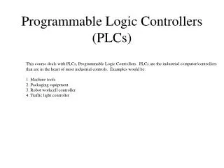
What is a PLC? • According to National Electrical Manufacturers’ Association a Programmable Logic Controller (PLC) is a digital electronic device that uses a programmable memory to store instructions and to implement functions such as logic, sequencing, timing, counting and arithmetic in order to control machines and processes. • Most widely used electronic devices in the control of production and assembly processes in most of the automated factories due to their simplicity and versatility. • It is a user-friendly, microprocessor-based, specialized computer carrying out control functions of many types and levels of complexity in industrial applications
Before the PLCs, automated manufacturing processes had to be controlled using hardware devices such as rotating cams in lathes. However in mid 1970s advances in micro-electronics have made a revolution in industrial control. Electronic programmable controller has replaced relay-based,hard-wired electrical systems.The first PLC systems were evolved from conventional computers in the mid 1970s and were mostly used in automotive industry.In the late 1980’s, PCs have been begun to be used in automatic industrial control, and this led a competition between PLCs and PCs. Brief Historical Background
What distinguishes a PLC from a PC predominantly is that Personal Computer Vs PLC • PLCs are constructed for a specific purpose with a smaller program, whereas PCs perform general tasks. • PLCs are sequential-type controllers which can process individual steps in a program in order.
Both PLCs and PCs have their particular strengths and weaknesses indeed.In general, what is seen and done in industrial control of today is that: PC vs. PLC • PLCs do majority of the control jobs. • PCs handle most of the data and mathematical functions.
PC vs. PLC PLCs can be programmed, controlled and operated by a person unskilled in operating computers. The PLC can operate any system that has input/output devices that go on and off as well as any system with variable input/outputs.
Advantages & Disadvantages of PLCs Disadvantages Advantages • High initial investment cost • Increase in flexibility • Faster implementation of changes and correction • Lower cost • Easy visualization of process running • Increased visual observations • Increased operation speed • Increased reliability and maintainability • Increased security • Reprogramming capability • Elimination of wiring.
PLC Characteristics • Large number of peripherals: 20..100 I/Os per CPU, high density of wiring, easy assembly. • Binary and analog input/output with standard levels • Located near the plant (field level), require robust construction, protection against dirt, water and mechanical threats, electro- magnetic noise, vibration, extreme temperature range (-30C..85C) • Programming: Either very primitive with hand-held terminals on the target machine itself, or with a lap-top able to download programs. • Network connection is becoming common, allowing programming on workstations. • Field bus connection for remote I/Os • Primitive Man-Machine interface, either through LCD-display or connection of a laptop over serial lines (RS 232).
General PLC Architecture RS 232 Ethernet CPU Real-TimeClock ROM flash EPROM serial port controller ethernet controller extension bus buffers parallel bus Fieldbus controller A/D converters D/A converters Digital Output Digital Input external I/Os signal conditioning power amplifiers signalconditioning relays direct inputs and outputs field bus
PARTS OF PLC • CPU module • Input and Output (I/O) modules • A power supply module • Peripheral equipment A PLC system contains four main parts:
CPU Module • This module consists of a central processing unit (CPU) which acts as the brain of the system and its Memory. • The CPU monitors the inputs, outputs and other variables and makes decisions based on instructions in the memory • It is supplied with a clock with a Frequency typically from 1 to 8 MHz • This frequency determines the Operating speed of the PLC and provides the timing and synchronization for all elements in the system. • Typical operations: • relay, counting, timing functions, data comparison, sequencing, and arithmetic operations.
Input/Output (I/O) Modules • I/O modules allow the PLC to read sensors and control actuators. • The input/output channels provide signal conditioning and isolation functions so that sensors and actuators can be generally directly connected to them without the need for other circuitry. • The primary function of a PLC’s input circuitry is to convert the signals provided by various switches and sensors into logic signals that can be used by the CPU. • Figure shows the basic form of an input channel. Common input voltages are 5 V and 24 V. Input Channel
Relay type of output OUTPUT MODULE • Output modules convert control signals from the CPU into digital or analog values that can be used to control various output devices. • Common output voltages are 24 V and 240 V. • Outputs are often specified as being of relay type, transistor type or triac type. • With the relay type, the signal from PLC output is used to operate a relay and so is able to switch currents of the order of few amperes in an external circuit and can be used for both d.c and a.c switching. Relays are, however, relatively slow to operate. • The transistor type of output uses a transistor to switch current through the external circuit. This gives a faster switching action. • Opto-isolators are used with transistor switches to provide isolation between the external circuit and the PLC. The transistor output is only for d.c switching. • Triac output can be used to control external loads, which are connected to the a.c power supply. Opto-isolators are again used to provide isolation. Transistor form of output
Power Supply Module • Power supply module provides power to the CPU and often provides power to drive sensors and low power actuators connected to I/O modules. • The power supplyoperateson acpower to provide the dc power required for the controller’s internal operation. It is designed to take either 115 or 220 VAC. • Some power supplies can take either voltage with a jumper switch for selection. The internal operation of I/O modules is also supported by the PLC power supply.
Peripheral Equipments • For preparing, storing and loading control programs, system monitoring • For communicating with other computers with which the PLC may be networked. • Some examples can be • Racks and chassis • For mounting other parts • Programmer/Monitor • To program instructions and monitor them
Peripheral Equipment • Hand-held programmer (loader) • CRT programmer • Operator console • Printer • Simulator • EPROM loader • Cassette loader • Graphics processor • Network communication interface • Programmer/Monitor (PM) • Racks and chassis
Various production equipment that can be connected to PLCs • Thermocouples • Strain gauge • Position encoder • Servo valves • Electrical motors • Linear motors • Stepping motors
Number Systems • PLC stores informationin the form of on or off conditions (1 or 0), referred to as bits. • Used either individually or to represent numerical values. • Understanding how these bits can be used to represent numerical values requires an understanding of the binary number system.
Decimal System • Ten digits 0, 1, 2, 3, 4, 5, 6, 7, 8, 9 • Base 10 • Weights: Powers of base 10 (1, 10, 100, 1000, ...)
Binary System • Two digits 0, 1 • Base 2 • Weights: Powers of base 2 (1, 2, 4, 8, 16, ...)
Logic 0, Logic 1 • A binary 0, also called logic 0, can be used to indicate that a switch is off • A binary (logic 1) can be used to indicate that a switch is on
Binary-Coded Decimal (BCD) • Humans often need to see values represented in decimal • Some input and output devices provide a decimal display where each decimal digit corresponds to four PLC binary inputs or outputs.
Hexadecimal • 16 digits 0, 1, 2, 3, 4, 5, 6, 7, 8, 9, A, B, C, D, E, F • Base 16 • Weights Powers of base 16 (1, 16, 256, 4096 ...) A = 10 • B = 11 • C = 12 • D = 13 • E = 14 • F = 15 The hexadecimal system allows the status of a large number of binary bits to be represented in a small space such as on a computer screen or programming device display. Each hexadecimal digit represents the exact status of four binary bits.
Decimal to Hexadecimal 1C Hexadecimal toDecimal 161 160 C 1 12x1=12 1x16=16 28
Terminology Sensors:Convert a physical condition into an electrical signal for use by the PLC. Sensors are connected to the input of a PLC
Terminology Actuators:Convert an electrical signal from the PLC into a physical condition. Actuators are connected to the PLC output.
Terminology Discrete Input: Also referred to as a digital input An input that is either on or off. Ex: Pushbuttons, toggle switches, limit switches, proximity switches, and contact closures
Terminology • With the pushbutton in the open state, no voltage is present at the PLC input (OFF condition) • When the pushbutton is depressed, 24 VDC is applied to the PLC input (ON condition)
Terminology • Analog Input: Continuous, variable signal. • Typical analog inputs: 0 to 20 milliamps, 4 to 20 milliamps, or 0 to 10 volts. • Depending on the level transmitter, the signal to the PLC can either increase or decrease as the level in the tank increases.
Terminology • Discrete Output: Either on or off • Ex. Solenoids, contactor coils, and lamps • A lamp can be turned on or off by the PLC output it is connected to.
Terminology • Analog Output: A continuous, variable signal. • The output may be as simple as a 0-10 VDC level that drives an analog meter. • Examples of analog meter outputs: speed, weight, and temperature
Terminology • Programming: Consists of instructions that accomplish one or more tasks. • The degree of complexity of a PLCs program depends upon the • complexity of the task to be performed • the number and type of input/output devices and • the types of instructions used • PLC Programs: • Ladder logic instructions • Statement lists • Function block diagrams
Terminology Ladder Logic: Uses components that resemble elements used in a line diagram format to describe hard-wired control. Ladder Logic Diagram:
Terminology • Statement List (STL): • The operation to be done is shown on the left. • The operand, the item to be operated on by the operation, is shown on the right. • The set of instructions in this statement list perform the same task as the ladder diagram.
Terminology • Function Block Diagrams • Each function has a name to designate its specific task. • Functions are indicated by a rectangle. • Inputs are shown on the left-hand side of the rectangle and outputs are shown on the right-hand side.
Terminology PLC Scan Cycle
Terminology Memory Size
Terminology • RAM (Random Access Memory) • Memory where data can be directly accessed at any address. • Data can be written to and read from RAM. • RAM is used as a temporary storage area. • RAM is volatile, meaning that the data stored in RAM will be lost if power is lost. • A battery backup is required to avoid losing data in the event of a power loss.
Terminology • ROM (Random Only Memory) • A type of memory that data can be read from but not written to. • Used to protect data or programs from accidental erasure. • ROM memory is nonvolatile. This means a user program will not lose data during a loss of electrical power. • ROM is normally used to store the programs that define the capabilities of the PLC.
Terminology • EPROM • (Erasable Programmable Read Only Memory) • Provides some level of security against unauthorized or unwanted changes in a program. • EPROMs are designed so that data stored in them can be read, but not easily altered. • Changing EPROM data requires a special effort. • UVEPROMs (ultraviolet erasable programmable read only memory) can only be erased with an ultraviolet light. • EEPROM (electronically erasable programmable read only memory), can only be erased electronically.
Terminology Mass Input/Output Copying Because, with continuous updating, there has to be a 3ms delay on each input, the time taken to examine several hundred input/output points can become comparatively long. To allow a more rapid execution of a program, a specific area of RAM is used as a buffer store between the control logic and the input/output unit. Each input/output has an address in this memory. At the start of each program cycle the CPU scans all the inputs and copies their status into the input/output addresses in RAM.
Terminology Mass Input/Output Copying cont’d • As the program is executed the stored input data is read, as required, from RAM and the logic operations carried out. • The resulting output signals are stored in the reserved input/output section of RAM. At the end of each program cycle all the outputs are transferred from RAM to the output channels. The outputs are latched so that they retain their status until next updating.
PLC Interfaces • RS-232C Interface • RS-422A Interface • IEEE-488/GPIB Bus Interface • Twisted-pair cable • Co-axial cable • Optical fibre cable
Specifications of a PLC The features of a typical small PLC, a Mitsubishi F2-20MR-ES • Power supply 110-120 V/220 - 240 V A.C, Single phase 50/60 Hz • Program language Ladder logic • Programming Capacity 1000 steps • Execution speed Average 7s/step • Program memory CMOS-RAM built-in, EPROM can be added • Battery back-up Lithium battery, approx. 5 year’s life • Timer 0.1 s timer: 24 points, on-delay timers (0.1 to 999 s) 0.01 s timer: 8 points, on-delay timers (0.01 to 99.9 s) • Counters 32 points, down counter (0 to 999) • Number of inputs 12 points, all optoisolated • Choice of output Relay output: relay isolated Transistor output: optoisolated Triac output: optoisolated
PLC Manufacturers • Siemens • Groupe Schneider • WAGO • Phoenix Contact • GE-Fanuc • Honeywell, • Invensys (Foxboro) • Rockwell, (Allen-Bradley,…) • Emerson (Fisher Control, Rosemount, Westinghouse) • Hitachi, Toshiba, Fujitsu, Yokogawa