Download
1 / 27
270 likes | 321 Views
Explore the design and types of communication links in Programmable Logic Controllers (PLC) systems. Learn about cables, connectors, and operational criteria such as frequency ranges. Enhance your knowledge of remote connections, twisted-pair cables, optical fibers, and more.

E N D
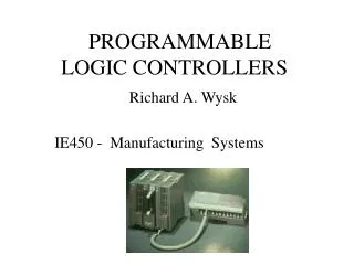
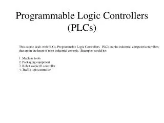
Programmable Logic Controllers LO1: Understand the design and operational characteristics of a PLC system
Learning Outcome 1 • LO1: Understand the design and operational characteristics of a PLC system • 1.3 evaluate the different types of communication link used in programmable logic control systems
BehaviouralObjectives • At the end of this session the students will be able to cables that meet… • selection criteria, description of features, frequency ranges, technology eg analogue, digital, wireless; cable eg twisted pairs, coaxial, fibre-optic, shielded/unshielded, categories, operational lengths; connector eg Bayonet-Neill-Concelman (BNC), registered jack (RJ-45), straight tip (ST), universal serial bus (USB) type A and type B; opto-isolator eg photodiode, phototransistor, thyristors, triacs
Remote Connections • When there are many inputs and outputs located considerable distances away from the PLC, though it would be possible to run cables from each such device to the PLC, a more economic solution is to use input / output modules in the vicinity of the inputs and outputs and use just a single core cable to connect each over the long distances to the PLC instead of using the multicore cable that would be needed without such I/O modules
Remote Connections Twisted-pair or screened cable, or fibre-optic cable, communications link PLC Input and Output connections Power cable Remote input / output module
PLC Networks • In some situations a number of PLCs may be linked together via a master PLC unit sending and receiving input / output data from other units Master PLC Communications Module Other I/O Modules PLC PLC Communications Port
PLC Networks • The distant PLCs do not contain the control programme since all the control processing is carried out by the master PLC
Cables • The cables used for communicating data between remote input/output modules and a central PLC or remote PLC and the master PLC are typically twisted-pair cabling, often routed through grounded steel conduit to reduce electrical ‘noise’.
Twisted Pair • Unshielded Twisted Pair (UTP) cabling is a type of wiring in which two conductors of a single circuit are twisted together for the purposes of cancelling out electromagnetic interference from external sources
Twisted Pair • Twisted pair cabling is often used in data networks for short and medium length connections because of its relatively lower costs compared to optical fibre and coaxial cable.
Twisted Pair • Shielded twisted pair (STP or STP-A) • Screened twisted pair (ScTP or F/TP) • Screened shielded twisted pair (S/STP or S/FTP)
Twisted Pair • Twisted pair cables are often shielded in an attempt to prevent electromagnetic interference. Because the shielding is made of metal, it may also serve as a ground. However, usually a shielded or a screened twisted pair cable has a special grounding wire added called a drain wire. • This shielding can be applied to individual pairs, or to the collection of pairs. When shielding is applied to the collection of pairs, this is referred to as screening.
Twisted Pair • Shielding provides an electric conductive barrier to attenuate electromagnetic waves external to the shield and provides conduction path by which induced currents can be circulated and returned to the source, via ground reference connection.
Skin-depth • As the frequency of the communicated signal increases then less and less of the cross-sectional area of the cable is used to transmit electricity. • At a particular frequency only the surface of the conductor actually conducts electricity. Above this frequency the cable will not conduct, rather it will radiate.
Coaxial Cables • Co-axial cable enables higher data rates to be transmitted and does not require the shielding of steel conduit
Coaxial Cables • Coaxial cable is used as a transmission line for radio frequency signals. • Its applications include feed-lines connecting radio transmitters and receivers with their antennas, computer network (internet) connections and distributing cable television. • Coaxial cable also provides protection of the signal from external electromagnetic interference.
Fibre Optic Cables • Fibre-optic cabling has the advantage of resistance to noise, small size and flexibility and is now becoming now widely used
BNC Connectors • The BNC connector(Bayonet Neill-Concelman (BNC) is a miniature quick connect / disconnect RF connector used for coaxial cable • It features two bayonet lugs on the female connector which mates with a quarter turn of the coupling nut to the male connector
BNC Connectors • BNC connectors normally work with frequencies up to 2 GHz and voltages up to 500 v • BNC connectors can be used on Ethernet networks both on cable interconnections and network cards
Registered Jack (RJ-45) • A Registered Jack (RJ) is a standarised physical network interface – standardising both both jack construction and wiring pattern – for connecting telecommunications or data equipment to a service provided by local exchange carrier or long distance carrier. • The physical connectors that Registered Jacks use are mainly of the modular connector and 50-pin miniature ribbon connector types. For example, RJ11 uses a 6P2C (6-position, 2-conductor) modular plug and jack.
Registered Jack (RJ-45) • Strictly, Registered Jackrefers to both the female physical connector (modular connector) and its wiring, but the term is often used loosely to refer to modular connectors regardless of wiring or gender, such as in Ethernet over twisted.
Straight Tip (ST)Connectors • An optical fiber connectorterminates the end of an optical fibre and enables quicker connection and disconnection than splicing. • The connectors mechanically couple and align the cores of fibres so light can pass. Better connectors lose very little light due to reflection or misalignment of fibres. • In all about 100 fibre optic connectors have been introduced to the market.
Universal Serial Bus(USB) • Universal Serial Bus (USB) is an industry standard developed in mid-1990 that defines the cables, connectors and communications protocols used in a bus for connection, communication and power supply between computers and electronic devices