Download

1 / 39
390 likes | 596 Views
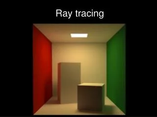
Ray Tracing. Photo-Realism. Created by David Derman – CISC 440. Created by Jan Oberlaender – CISC 640. Created by Jan Oberlaender – CISC 640. Created by Donald Hyatt http://www.tjhsst.edu/~dhyatt/superap/povray.html. RAY Tracing. Ray Tracing :

E N D
Photo-Realism Created by David Derman – CISC 440
Created by Donald Hyatt http://www.tjhsst.edu/~dhyatt/superap/povray.html
RAY Tracing • Ray Tracing : Ray tracing is a method for calculating the path of waves or particles through a system. RAY
Types of Rays Ray tracing in Physics: Which is used for analyzing optical and other systems.
Types of Rays Ray tracing Graphics : which is used for 3D image generation
How it Works Ray Tracing : technique use for generating an 3-D image by Tracing the path of Light through Pixels in an Image Plane and simulating the effects of its encounters with virtual objects.
Introduction • Ray Tracing based rendering method for generating realistic images on the computer. • In ray tracing, a ray of light is traced in a forward and backwards direction.
Overview • Forward Ray tracing • Rays from light source bounce of objects before reaching the camera • Computational wastage • Backward Ray tracing • Track only those rays that finally made it to the camera Courtesy: Angel
Ray Tracing • We start from the eye or camera and trace the ray through a pixel in the image plane into the scene and determine what it intersects. • The pixel is then set to the color values returned by the ray. • If the ray misses all objects, then that pixel is shaded the background color.
Ray Tracing • Sometimes a ray misses all objects
Ray Tracing (contd.) • Sometimes a ray hits an object
Ray Tracing (contd.) • Sometimes Ray intersect point`s and Reflect Back To Light Source.
Ray Tracing (contd.) • Shadow rays intersect another object • First intersection point in shadow of the second object
Ray Tracing (contd.) • Reflected ray generated at point of intersection • Tested with all the objects in the scene
Ray Tracing (contd.) • Local illumination model applied at the point of intersection
Ray Tracing (contd.) • Transparent object • Generate a transmitted ray and test against all objects in the scene
Effects Of Ray on Object When Ray Hit the Surface of an Object it produce different effect`s. • Reflection. • Refraction/Transmission. • Shadow
Reflection Created by David Derman – CISC 440
Reflection Created by David Derman – CISC 440
Reflection Created by David Derman – CISC 440
Reflection Created by David Derman – CISC 440
Refraction • Bending of light rays as it crosses interface between media having different refractive indices • Snell’s Law c1,c2 – Refractive index Courtesy F.S. Hill, “Computer Graphics using OpenGL”
Adding shadows Shadow Feelers : A shadow feeler is a ray sent from a point u on the surface of an object towards a light source to determine whether the light is visible from the point u or whether it is occluded by intervening objects.
Shadow Feeler • If the shadow feeler hits an object before reaching the light, then the light is presumed to be occluded by the object so that the point is in a shadow.
Angle Of incident <180 <90
Ray object intersection • Equation of a ray • “S” is the starting point and “c” is the direction of the ray, t is angle • Given a surface in implicit form F(x,y,z) • plane: • sphere: • cylinder: • All points on the surface satisfy F(x,y,z)=0
Ray Tracing Algorithm • Begin tracing. • Construct a ray through each pixel in the scene. • Pixel color = result of tracing the ray • Tracing the ray • Find intersection of ray with closest object in the scene. • Compute intersection point and normal at the intersection point. • Shade the point. • Shade the point • For each light… • Determine if point is in shadow relative to light source. • Using illumination model, determine color at the intersection point.
Ray Tracing Algorithm integer i, j; ray r; { defines starting point and direction of ray } point eyePt, hitPt; shape pointer hitObjP; real array I [XMIN .. XMAX, YMIN .. YMAX]; for i:=YMIN to YMAX do for j:=XMIN to XMAX do begin ComputeRay (i,j,r); FirstIntersection1 (r,hitPt,hitN,hitObjP); if hitObjPπ nil then I[i,j] := Shade (eyePt,nil,hitPt,hitN,hitObjP,1) else I[i,j] := background end; procedure ComputeRay (integer i, j; ref ray r) { Computes the ray r (in world coordinates) from the eye defined by the (i,j)th pixel } procedure FirstIntersection1 (ray r; ref point hitPt, hitN; ref shape pointer hitObjP) { Returns a pointer hitObjP to the closest object intersected by the ray r, the point hitPt on that object where the ray intersects it, and the surface normal hitN at that point. Use bounding boxes for projected objects in view plane to speed up computation. }