Download
1 / 25
250 likes | 391 Views
Ray Tracing. Jerry Sui Adam Conner. Part I – Introduction to Ray Tracing. Final Product. Part I – Introduction to Ray Tracing. Trace the rays backward from the viewpoint through each pixel and into the scene (reverse direction of light propagation).

E N D
Ray Tracing Jerry Sui Adam Conner
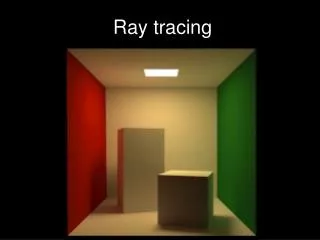
Part I – Introduction to Ray Tracing Final Product
Part I – Introduction to Ray Tracing • Trace the rays backward from the viewpoint through each pixel and into the scene (reverse direction of light propagation). • Find intersection point that is closest to eye. • Compute color at intersection. Ray Tracing is global lighting model.
Part I – Introduction to Ray Tracing Cast rays into the scene: Ray: a point (xo, yo, zo) and the direction (unit vector)
Part II – Ray-object Intersection • Whether there is an intersection (with object surface). • If yes, give me the distance between viewpoint and the point of intersection (so that we can calculate the position of the intersection point). • ---Find intersection that is closest to the viewpoint.
Part II – Ray-object Intersection Ray-plane intersection: ax + by + cz + d = 0 n = (a, b, c) Intersection with X-axis: -d/a Intersection with Y-axis: -d/b Intersection with Z-axis: -d/c
vd po pd n Part II – Ray-object Intersection vd = (xd, yd, zd) direction vector (unit); pd = po + tvd a(xo + txd) + b(yo + tyd) + c(zo + tzd) + d = 0 Solve: t = -(axo+byo+czo+d) / (axd+byd+czd) = -(n po + d) / n vd
Part II – Ray-object Intersection Sphere, Box…etc. Most of the work in ray tracing goes into calculation of intersections between rays and surfaces. Calculations of some ray-object intersections could be pretty hard.
Part III – Color at Intersection The color at the intersection point depends on • Lights in scene • Material properties of the object.
Part III – Color at Intersection • Illumination: • Phong reflection model • Reflection • Transmition (refraction) light • Shadow need recursion
Part III – Color at Intersection • Phong reflection model: • Diffuse: • Calculated using the diffuse component of the light source. • Ambient • Calculated using the ambient light in the scene. • Specular reflection • Calculated by taking the dot product of the reflection ray with the rays direction vector, and raise the result to a power.
Part III – Color at Intersection • Reflection: • Mirror-like object reflection • Outside phong reflection model • Recursive; additional secondary rays generated for each intersection • Secondary ray acts as primary ray, which may in turn generate additional secondary rays. • Primary ray: ray shot out from the viewpoint. • Secondary ray: any ray the is not a primary ray.
n I T Part III – Color at Intersection • Transmission (refraction): Snell’s Law:
Part III – Color at Intersection • Transmission:
Part III – Color at Intersection • Transmission: • Absorbency Coefficient: e = 2.718… (base of natural logarithm) R: transparency factor (0, 1) D: distance the ray travelled.
Part III – Color at Intersection • Anti-aliasing: • Shoot multiple rays through a pixel (to different position inside a pixel), and then average the colors returned by the rays. That is the final color of the pixel.
Part III – Color at Intersection • Shadows: • Given an intersection, shoot a ray to each light source and trace it to see if it intersects with anything along the way. • If the shadow ray makes it to the light source, then the intersection is not in the shadow of that light. Otherwise, it is.
Part III – Color at Intersection • Shadows: • Area Lights: • Area light can be seen as if it is comprised of multiple point lights. • Each point light within an area light gives off a fraction of the total light for the area light. • When calculating shadows from area light, each intersection point fires a ray for each part of the area light. For each of these rays which fails to reach the area light, the sum of those fractions of light represent the shadow at the intersection point cast from the area light.
Part III – Color at Intersection • Shadows: • Soft Shadows (noise): • Eliminate banding • Done by using multiple shadow rays for each area light grid position, each with random offset.
Part IV – Future Research Possibilities • Optimization (acceleration) • Distributed computing • Better illumination model • Real-time ray tracing ……